14
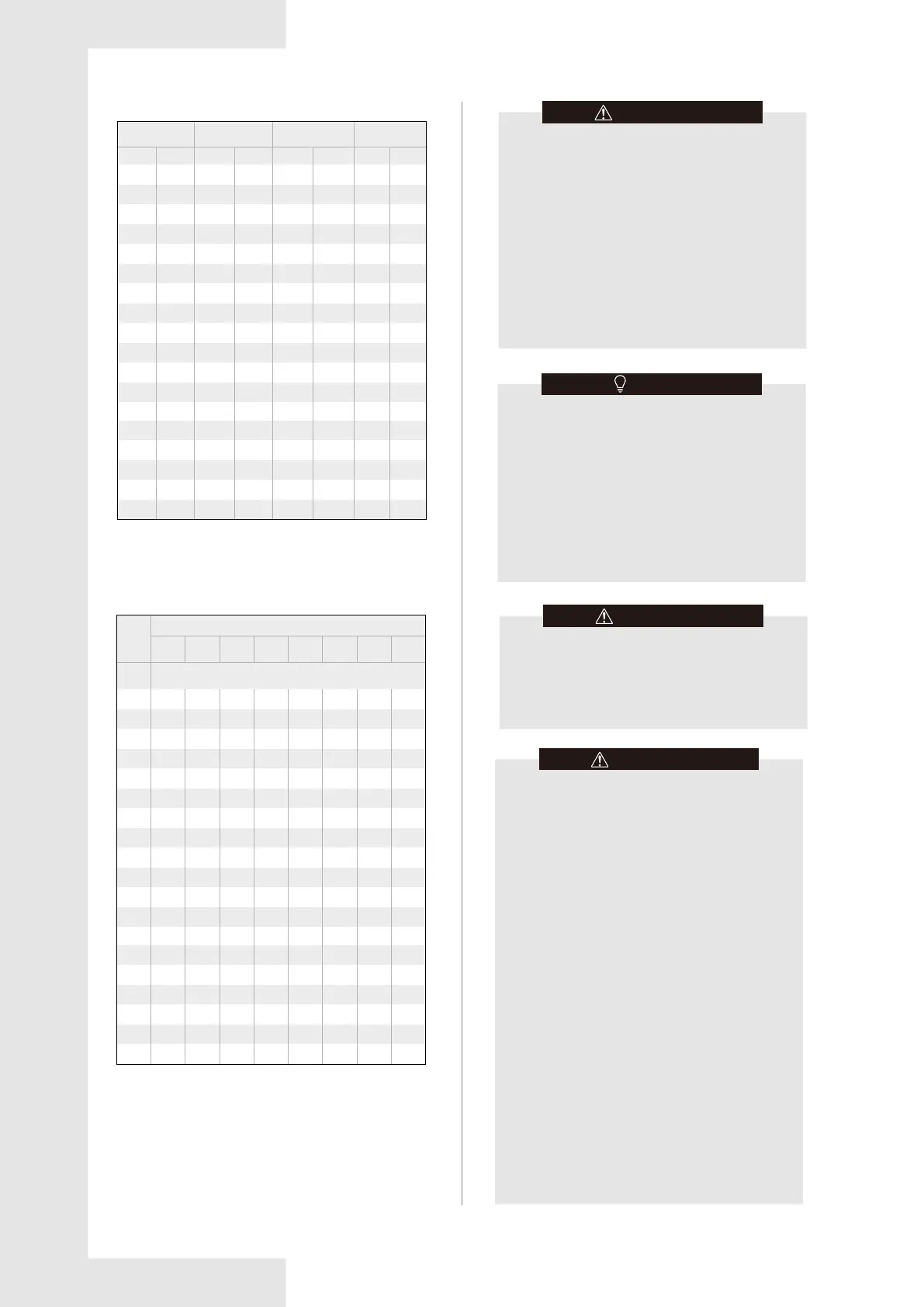
Table 3-4
The minimum circulation airflow
The allowable maximum refrigerant charge of
the Table 3-2 or the required minimum room
area of the Table 3-3 is available only if the
following conditions are met:
Minimum velocity of 3.28 ft/s, which is calculated
as the indoor unit airflow divided by the nominal
face area of the outlet. The grill area shall not be
deducted.
Minimum airflow rate must meet the
corresponding values in Table 3-4, which is
related to the actual refrigerant charge of the
system (Mc).
R454B refrigerant leakage sensor is configured.
CAUTION
The maximum refrigerant limit described above
applies to unventilated areas. If adding additional
measures, such as areas with mechanical
ventilation or natural ventilation, the maximum
refrigerant charge can be increased or the minimum
room area can be reduced.
R454B refrigerant leakage sensor is configured
for the indoor unit, and meets the incorporated
circulation airflow requirements,the maximum
refrigerant charge or minimum room area can be
determined according to Table 3-2 or Table 3-3.
NOTE
If the actual room area, air outlet height, and
refrigerant charge amount are not reflected in
the above table, more severe cases need to be
considered according to the data in the Table
3-1, 3-2, 3-3, 3-4.
CAUTION
Instruction for installation of the critical-to-safety
wiring connection of the leak detection sensor or
leak detection system to the furnace assembly.
The wiring shall be not less than 18 AWG with a
minimum insulation thickness of 1.58 mm or
protected from damage. Critical-to-safety wiring
is any field installed wiring necessary to fulfill the
requirements of Table 3-3 in the event of
detection of a leak.
Shall not be installed on furnaces with an
inductive electrical greater than Le as calculated
as follows:
the switched electrical load (Le) in kVA is less
than or equal to:
- Le = 5 x (6,7/Su)4 when breaking all phases;
- Le = 2,5 x (6,7/Su)4 when breaking two legs
of a three phase load, or when breaking one or
two legs of a single phase load.
where
Le is the switched inductive electrical load in
kilovoltamperes (kVA);
Su is the burning velocity of a refrigerant in
centimeters per second (cm/s).
Detection of a leak shall turn on the indoor fan at
the highest available speed or turn it on to not
less than Qmin as shown in Table 3-4.
CAUTION
Mc
Qmin
lb-oz kg
m
3
/h
Mc
Qmin
lb-oz kg
2-2
2-9
3-0
3-7
3-15
4-6
4-13
5-4
5-11
6-2
6-9
7-0
7-7
7-15
8-6
8-13
9-4
9-11
10-2
10-9
11-0
11-7
11-14
12 -5
12-12
13-3
13-10
14-1
14-8
14-15
15-6
15-14
16-5
16-12
17-3
1.0
1.2
1.4
1.6
1.8
2.0
2.2
2.4
2.6
2.8
3.0
3.2
3.4
3.6
3.8
.0
4.2
4.4
4.6
4.8
5.0
5.2
5.4
5.6
5.8
6.0
6.2
6.4
6.6
6.8
7.0
7.2
7.4
7.6
7.8
CFM
m
3
/h
CFM
59
71
83
95
107
119
131
143
155
167
179
191
203
215
227
239
251
263
275
287
298
310
322
334
346
358
370
382
394
406
418
430
442
454
466
100
121
141
161
182
202
223
243
263
284
304
325
345
365
386
406
426
447
467
488
506
527
547
567
588
608
629
649
669
690
710
731
751
771
792
Table 3-5
Charge
lb
Minimum Conditioned Space(ft²)
2
3
4
5
6
7
8
9
10
11
12
13
14
15
16
17
18
19
20
39
59
79
99
119
138
158
178
198
218
237
257
277
297
317
336
356
376
396
33
50
66
83
100
116
133
149
166
183
199
216
232
249
266
282
299
315
332
42
63
85
106
127
148
169
190
211
232
254
275
296
317
338
359
380
402
423
35
53
70
88
105
123
140
158
175
193
211
228
246
263
281
298
316
333
351
45
68
91
113
136
159
181
204
227
249
272
295
318
340
363
386
408
431
454
37
56
74
93
112
130
149
167
186
205
223
242
260
279
298
316
335
353
372
47
71
94
118
141
165
188
212
235
259
282
306
330
353
377
400
424
447
471
49
73
98
122
147
171
196
220
245
269
294
318
343
367
392
416
440
465
489
If the altitude of installation is higher than 2000 ft, the
required minimum room area follow as Table 3-5.
2001-
4000
4001-
6000
8001-
10000
10001-
12000
12001-
14000
14001-
15000
above
15000
6001-
8000
Altitude(ft)