6 18-AD47D1-1B-EN
Installer’s Guide
E. RECOMMENDATION:
If a coil is part of the total system installation, use the Installer’s
Guide packaged with the furnaces, outdoor sections, and
thermostat for physically installing those components.
F. FURNACE IN UPFLOW POSITION :
1. UPFLOW COIL CONVERSION: While not required,
optional removal of some coil components will maximize
airow eciency.
a. Remove the coil by sliding the coil out of the coil
enclosure.
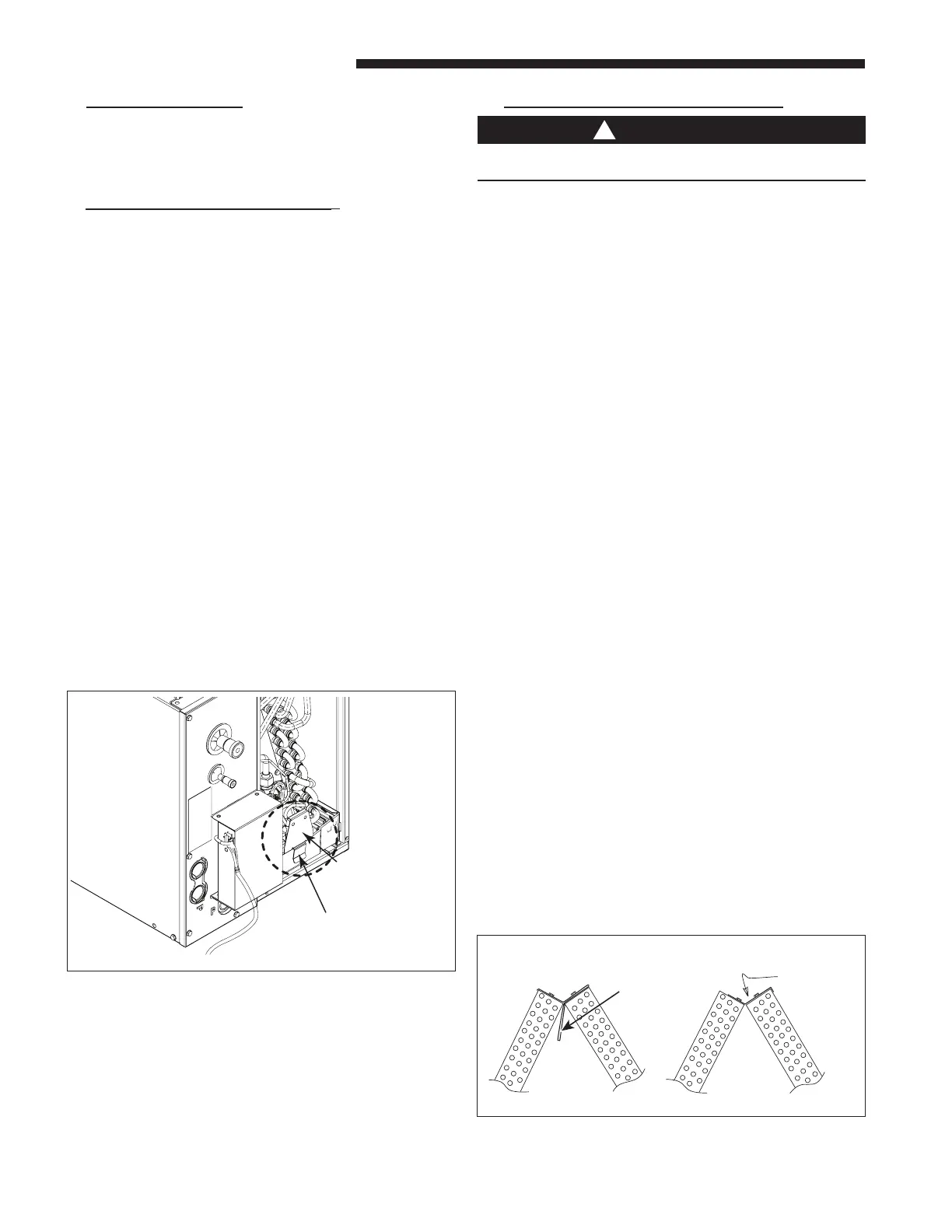
b. Optional but recommended: Remove the factory
installed two-piece bae assembly from the top of
the coil by removing the 5/16” hex head screws. See
Figure 3. Replace only the top bae using the same
screws previously provided.
c. Optional but recommended: On 5TXCA009AS and
5TXCD010AS only, remove the (2) outer water diverter
baes by removing the 5/16” hex head screws. See
Figure 10.
d. Optional for maximum eciency: Remove the
horizontal drain pan from the coil and discard.
2. UPFLOW GAS FURNACE
a. Apply gasket material (duct seal eld supplied) to ALL
mating surfaces between the furnace and the coil case.
b. Set the coil case on top of the furnace. Connect the
ductwork to the coil case using eld supplied screws.
c. Secure the coil case to the furnace using factory
provided standos and screws. See Figure 4.
Seal for air leaks as required.
d. Ensure the sensor is secured to the primary drain pan
as shown in Figure 2.
Refrigerant Sensor
should be seated
fully on pan
Dimension from the bottom of
the Drain Pan to the bottom of
the Sensor should be 0.8" max
Figure 2
G. FURNACE IN DOWNFLOW POSITION:
To prevent damage to pan, ensure Heat Shield is
assembled to Horizontal Drain Pan. See Figure 9.
1. DOWNFLOW COIL CONVERSION: While not required,
optional removal of some coil components will maximize
airow eciency.
a. Remove the coil by sliding the coil out of the coil
enclosure.
b. Optional but recommended: Remove the factory
installed two-piece bae assembly from the top of
the coil by removing the 5/16” hex head screws. See
Figure 3. Replace only the top bae using the same
screws previously provided.
c. Optional for maximum eciency: Remove the
horizontal drain pan from the coil and discard.
d. Ensure the sensor is secured to the primary drain pan
as shown in Figure 2.
2. DOWNFLOW GASKET INSTALLATION (OPTIONAL): For
unusually humid applications that expect prolonged operation
above 70% RH, it is recommended to use the BAYGSKT001A0
gasket kit to prevent water from forming on the bottom of the
drain pan and dripping into the supply ductwork.
a. Lay the coil on its back side.
b. Locate the 4" wide gasket material found in
BAYGSKT001A0.
c. Attach the 4" gasket material to three sides of the
bottom of the drain pan as shown in Figure 5. Make
sure to start by matching up the edge of the gasket
material to the inner edge of the drain pan by the coil
ns and working outwards.
d. The gasket material can be cut or ripped easily so that
it can be tailored to t. The gasket material must cover
the three sides along the entire length of the coil as
shown in Figure 5.
3. DOWNFLOW GAS FURNACE
When a coil is used with a downow furnace, a subbase
is not required between the coil case and combustible
ooring.
a. Place the coil case on the furnace supply air plenum.
b. Secure the coil case to the plenum.
c. Set the furnace on top of the coil case, making sure
that the back side of the discharge opening is snug up
against the duct ange at the top rear of the coil case.
d. Secure the coil case to the furnace and seal for air
leaks as required.
Figure 3