18-AD47D1-1B-EN 9
Installer’s Guide
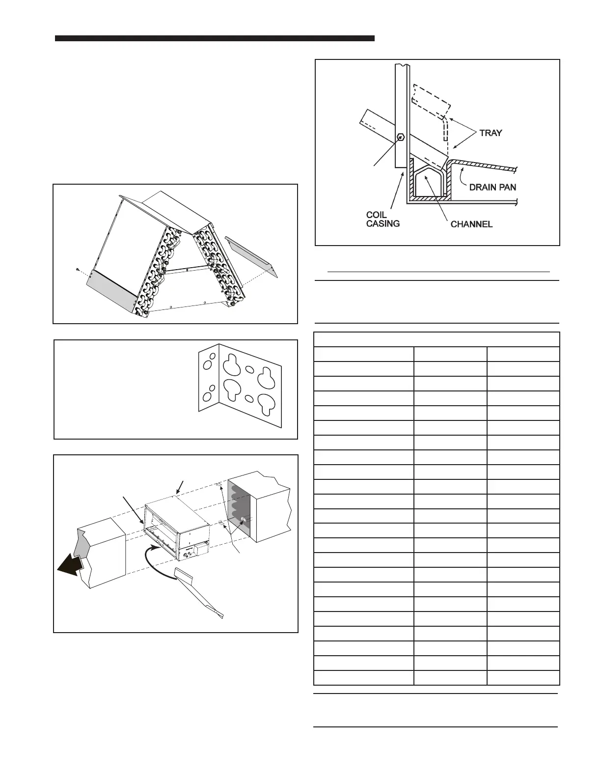
Figure 10
Figure 11
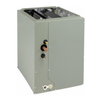
CASED COIL CONNECTION
BRACKET FOR DOWNFLOW
FURNACE IN HORIZONTAL
Standoffs and screws (See Figure 4) are included with the
cased coils for attachment to the furnace. There are clearance
alignment holes near the bottom of the coil wrapper. Drill
screws are used to engage the top flanges of the furnace.
The standoff is inserted into the cabinet alignment hole (See
Figure 4). The drill screws are inserted through the standoffs
then screwed into the furnace top flange. The coil is always
placed downstream of the furnace airflow. The coil and furnace
must be fully supported when used in the horizontal position.
The standoffs and screws are strictly for securing alignment,
not for support in horizontal.
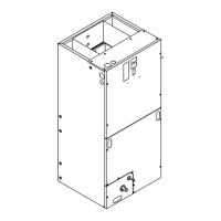
AIRFLOW
FURNACE
DUCT
SPLASH
GUARD
CASED COIL
APEX OF COIL POINTS
AWAY FROM FURNACE
BRACKETS SHIP WITH DOWNFLOW
NON-CONDENSING FURNACES.
REQUIRED FOR ALIGNMENT
ON SOME HORIZONTAL INSTALLATIONS.
Figure 12
Horizontal Left Installation
Maximum airflow setting, CFM
Coil Upflow Horizontal Left
5TXCA002AS3HCA 900 800
5TXCA032AS3HCA 1350 1125
5TXCB003AS3HCA 1125 1000
5TXCB004AS3HCA 1350 1200
5TXCB006AS3HCA 1350 1200
5TXCC005AS3HCA 1800 1600
5TXCC007AS3HCA 1800 1600
5TXCD008AS3HCA 1800 1600
5TXCC009AS3HCA 2250
2000
5TXCD010AS3HCA 2250 2000
Coil Downflow Horizontal Right
5TXCA002AS3HCA 750 900
5TXCA032AS3HCA 1200 1350
5TXCB003AS3HCA 925 1125
5TXCB004AS3HCA 1100 1350
5TXCB006AS3HCA 1100 1350
5TXCC005AS3HCA 1475 1800
5TXCC007AS3HCA 1475 1800
5TXCD008AS3HCA 1475 1800
5TXCC009AS3HCA 1850 2250
5TXCD010AS3HCA 1850 2250
J. MAXIMUM AND MINIMUM AIRFLOW SETTINGS:
NOTE:
Water blow-off could occur in certain installation
positions if the airow setting exceeds the maximum
values listed.
NOTE:
The TXV setting on this unit may run high superheat
(15-25°F) by design when measured at the outdoor unit.
Figure 13