8
WSHP-SVX014J-EN
General Information
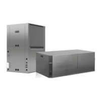
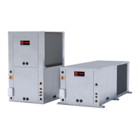
Unit Description
Before shipment, each unit is leak tested, dehydrated,
charged with refrigerant and run tested for proper control
operation.
Air-to-Refrigerant Coil
The air-to-refrigerant coil is aluminum fin, mechanically
bonded to the copper tubing.
Water-to-Refrigerant Coil
The water-to-refrigerant coil is a copper or cupro-nickel
(option) and steel tube (tube-within-a-tube) design, leak
tested to assure there is no cross leakage between the
water tube (copper/cupro-nickel) and refrigerant gas (steel
tube).
Table 1. High/low pressure switch
Trip Recover Unit
LP 40 +/-4 56 +/-4 psig
HP 650 +/-10 550 +/-10 psig
Controls
The available control type is a Deluxe 24V control option, a
Symbio™ 400-B/Tracer® UC400-B BACnet® control
option for all unit sizes.
All power wiring to the equipment is made at the unit’s
compressor contactor or optional disconnect switch for the
EXH/V 0.75 to 6 ton units and the DXH/V 2 to 6 ton units.
For units without the disconnect switch, the power wiring
needs to be connected to the screw terminals of the
compressor contactor. All low-voltage wiring is made at the
unit’s low voltage terminal plug.
System Input Devices and
Functions
A thermostat, zone sensor, or building automation system
is required to operate the water-source heat pump. The
flexibility of having several mode capabilities depends upon
the type of sensor and/or remote panel selected.
Troubleshooting and connection diagrams for the 24V
control systems may be located in the back of this manual.
All digital control troubleshooting tips and connection
diagrams are located in BAS-SVX065*-EN (UC400-B).
Deluxe 24V Controls (option)
Units containing the Deluxe 24V control design will
incorporate a microprocessor-based control board. The
Trane microprocessor board is factory wired to a terminal
plug to provide all necessary terminals for field connection.
The deluxe board is equipped with a random start relay,
anti-short cycle timer, brown out protection, compressor
disable, condensate overflow, unit safety control,
diagnostics, and a generic relay (which may be available
for field use).
Symbio™ 400-B/Tracer® UC400-
B (option)
The Symbio 400-B/UC400-B is a BTL Listed BACnet®
controller that can operate stand- alone or within a Building
Automation System (BAS) such as Tracer® SC+. For
installation, operation, and maintenance, see BAS-
SVX065*-EN (UC400-B).
Pump Module (Field Installed
Accessory)
The pump module shall consist of either a single or dual 1/6
HP cast iron pump and a brass three-way shut-off valve.
The pump module kits shall contain the necessary
components for the installation, operation and maintenance
of the water circuit of a closed-loop distributed pumping
application.
Waterside Economizer (Option)
Instructions for mechanical connection of the waterside
economizer to the water-source heat pump may be found
in the dimensional section of this manual.
The waterside economizer is designed to begin
economizing mode when water temperatures fall below the
field adjustable temperature of 25, 35, 45, 55 or 60°F (for
the Deluxe control option), or below the programmed set-
point (for the Symbio™ 400-B/UC400-B control option).
When the temperature is less than the setpoint, fluid will
flow into the economizing coil, while simultaneously halting
mechanical operation of the compressor. Mechanical
cooling will continue on a call for a second stage from the
thermostat or system control. Entering water temperature
sensor is factory provided for field installation on the
entering water side of the coil.
Boilerless Control/Electric Heat
(Option)
This option targets building designs that do not incorporate
a boiler to heat the loop system. During a heavy heating
load, the loop temperature may begin to fall. As the loop
temperature decreases, the heating capacity of the heat
pump will also decrease. In the heating mode, when the
loop temperature falls below 55°F (factory setting), the
electric heater is energized, and the compressor is locked
out. The system’s electric heat source will continue to be
utilized for primary heating until the loop temperature rises
 Loading...