Table 18. Kit contents LVR01100
# Qty Per Component Part Component Description
1 4 572095370100 PANEL; LOUVER
2 16 X25030266010 SCREW; M6 X 16MM HEX CAP
3 2 572095360100 SUPPORT; LOUVER
4 127 X25020604010 SCREW;M8 X 1.25MM X 16MM
5 12 572055590100 LOUVER; UNIT SIDE CGAM
6 1 572116120100 SUPPORT; LOUVER
7 1 572094890100 POST; LOUVER
8 2 572055570100 LOUVER; LOWER END CGAM
9 1 572116160100 PANEL; TOP CONTROL PANEL
10 1 572116130100 SUPPORT; PANEL
12 1 572116030100 PANEL; UNIT END
13 1 572116070100 PANEL; UNIT END
14 1 572116080100 PANEL; BPHE INLET/OUTLET
15 2 572116100100 PANEL; PHR INLET/OUTLET
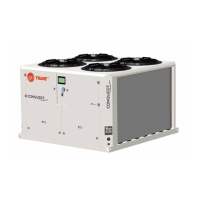
Figure 9. CGAM040–052 ton (V1 units); 1 of 2
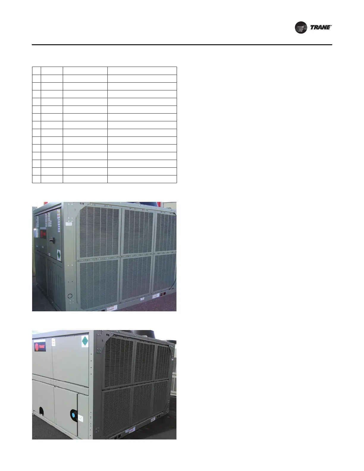
Figure 10. CGAM040–052 ton (V1 units); 2 of 2
Installation
PART-SVN228B-EN 15
1. Install four side louver supports (Figure 11, p. 16,
Item 1), two on each side of unit, with provided
M6 X 16 screws (Figure 11, Item 2).
2. Install center louver supports (Figure 11, Item 3) to
each
side o
f unit with provided M8 X 16 screws
(Figure 11, Item 4).
Note: Do
not use an impact gun when installing
plastic louvers.
3. In
stall six upper louvers (Figure 11, Item 5), three each
side, with provid
ed M8 X 16 screws (Figure 11, Item 4).
4. Install lower end louver support (Figure 11, Item 6)
with provided M8 X 16 screws (Figure 11, Item 4).
5. Install lower end louver post (Figure 11, Item 7) with
provid
ed M8 X 16 screws (Figure 11, Item 4).
6. Install lower end louvers (Figure 11, Item 8) with
provided M8 X 16 screws (Figu
re 11, Item 4).
7. Install top control panel strip (Figure 11, Item 9) with
provid
ed M8 X 16 screws (Figu
re 11, Item 4).
8. Install lower support (Figure 11
, Item 10) on end of unit
with provided M8 X 16 screws (Figure 11, Item 4).
Note: Installation of Item 11 in Step 9 i
s only required
on units that do NOT have heat recovery option.
9. Install center rear end support panel (Figure 11,
Item 11) with provided M8 X 16 screws (Figure 11,
Item 4).
10. Install the three lower un
it end panels (Figure 11,
Item 12, Item 13, and Item 14) with provided M8 X 16
screws (Figure 11, It
em 4).
11. Install upper unit end panels (Figure 11, Item 15 and
Item 16) with provided M8 X 16 screws (Figure 11,
Item 4).
12. Install six lower louvers (Figure 11, Item 5), three each
side, with pro
vided M8 X 16 screws (Figure 11, Item 4).