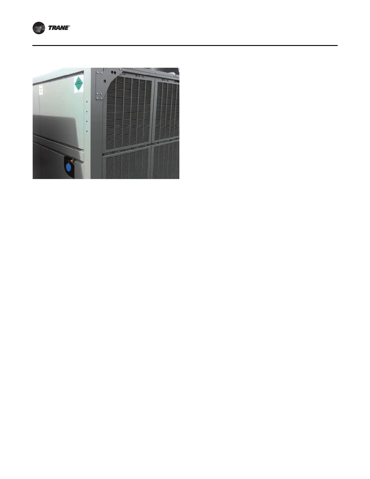
Figure 13. CGAM060–070 ton (V2 units); 2 of 2
Installation
18 PART-SVN228B-EN
1. Install four center louver supports, (Figure 14, p. 19,
Item 1), two to each side of unit, with provided M8 X 16
screws (Figure 14, Item 2).
Note: Do n
ot use an im
pact gun when installing
plastic louvers.
2. Install eight upper louvers (Figure 14, Item 3), four
each
side, with
provided M8 X 16 screws (Figure 14,
Item 2).
3. Install lower end louver
support (Figure 14, Item 4)
with provided M8 X 16 screws (Figure 14, Item 2).
4. Install lower end louver post (Figure 14, Item 5) with
pr
ovided M8 X 16 screws
(Figure 14, Item 2).
5. Install lower end louvers (Figure 14, Item 6) with
provided M8 X 16 screws
(Figure 14, Item 2).
6. Install top control panel strip (Figure 14, Item 7) with
provided M8 X 16 screws
(Figure 14, Item 2).
7. Install lower support (Figure 14, Item 8) on end of unit
with provided
M8 X 16 screws (Figure 14
, Item 2).
Note: Installation of Item 9 in Step 8 is on
ly required
on units that do NOT have heat recovery option.
8. Install center rear end su
pport panel (Figure 14, Item 9)
with provided M8
X 16 screws (Figure 14, Item 2).
9. Install the three lower unit end panels (Figure 14,
Item 10, Item 11, an
d Item 12) with provided M8 X 16
screws (Figure 14, Item 2).
10. Install upper unit end panels (Figure 14, Item 13 and
Item 14) with provided M8 X 16 screws
(Figure 14,
Item 2).
11. Install eight lower
louvers (Figure 14, Item 3), four each
side, with provided M8 X 16 screws (Figure 14, Item 2).