Table 6. Kit number LVR01090
# Qty Per Component Part Component Description
1 2 572095370100 PANEL; LOUVER
2 1 572095360100 SUPPORT; LOUVER
3 72 X25020604010 SCREW;M8 X 1.25MM X 16MM
4 8 X25030266010 SCREW; M6 X 16MM HEX CAP
5 6 572055590100 LOUVER; UNIT SIDE CGAM
6 1 572051000100 PANEL; BACK SIDE
7 1 572095690100 SUPPORT; BACK SIDE
8 1 572097980100 PANEL; BACK SIDE W/PP
9 1 572050910100 PANEL; BACK SIDE W/PP
10 1 572054540100 PANEL; LEFT SIDE
11 1 572050900100 PANEL; FRONT SIDE
12 1 572054540100 PANEL; LEFT SIDE
Table 7. Kit number LVR01091
# Qty Per Component Part Component Description
1 2 572095370100 PANEL; LOUVER
2 1 572095360100 SUPPORT; LOUVER
3 78 X25020604010 SCREW;M8 X 1.25MM X 16MM
4 8 X25030266010 SCREW; M6 X 16MM HEX CAP
5 6 572055590100 LOUVER; UNIT SIDE CGAM
6 1 572051000100 PANEL; BACK SIDE
7 1 572095690100 SUPPORT; BACK SIDE
8 1 572097980100 PANEL; BACK SIDE W/PP
9 1 572050910100 PANEL; BACK SIDE W/PP
10 1 572054540100 PANEL; LEFT SIDE
12 1 572054540100 PANEL; LEFT SIDE
14 1 572097020100 PANEL; FRONT SIDE W/VFD
15 1 572097030100 PANEL; FRONT SIDE W/VFD
16 1 572097010100 SUPPORT; FRONT SIDE
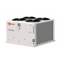
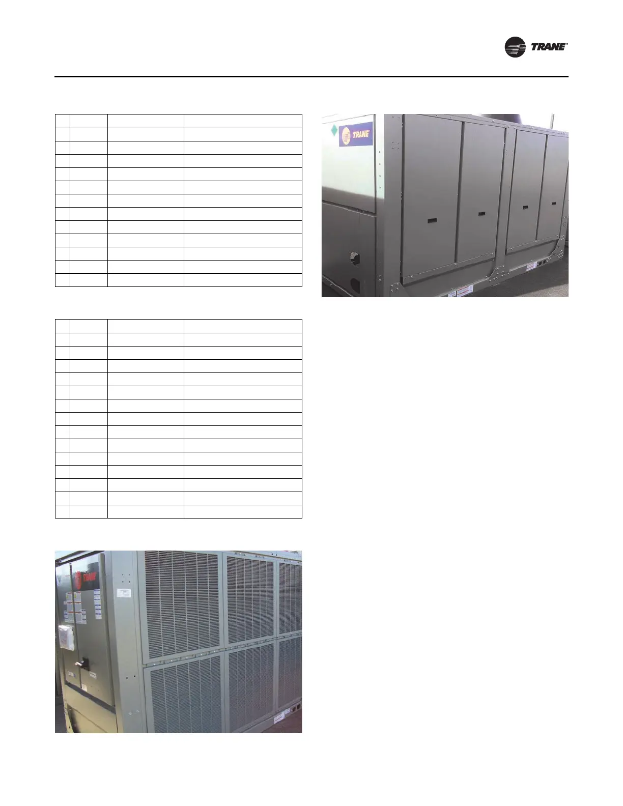
Figure 1. CGAM020–026 ton (S1 units); 1 of 2
Figure 2. CGAM020–026 ton (S1 units); 2 of 2
Installation
PART-SVN228B-EN 7
1. Install two side louver supports (Figure 3, p. 8, Item 1)
to unit with provided M6 X 16 screws (Figure 3,
Item 4).
2. Install center louver support (Figure 3, Item 2) with
provid
ed M8 X 16 screws (Figu
re 3, Item 3).
Note: Do not use an impact gun when installing
plastic louvers.
3. In
stall three upper louvers (Figure 3, Item 5) with
provided M8 X 16 screws (Figu
re 3, Item 3).
4. Install upper backside panel (Figure 3, Item 6) with
provid
ed M8 X 16 screws (Figu
re 3, Item 3).
5. Install lower back side panel su
pport (Figure 3, Item 7)
with provided M8 X 16 screws (Figure 3, Item 3).
6. Install left back side panel (Figure 3, Item 8) and right
back side pa
nel (Figure 3, Item 9) with provided
M8 X 16 screws (Figure 3, Item 3).
7. Install two lower left side panels (Figure 4, p. 9, Item 10
an
d Item 12) with provided M8 X 16 sc
rews (Figure 4,
Item 3).
8. If unit has partial heat recovery option, also install
a
ddi
tional left side panel (Figure 4, Item 13) with
provided M8 X 16 screws (Figure 4, Item 3).
Note: Front panel, Item 11 in Step 9, is o
nly used on
units that do NOT have the flow control option.
Item 14, Item 15, and Item 16 are used on units
with the flow contro
l option.
9. Install front panel (Figure 4, Item 11) with provided
M8 X 16 screws (Figure 4, Item 3).
10. If unit has the flow control op
tion install the three front
panels (Figure 4, Item 14, Item 15, and Item 16) with
provided M8 X 16 screws (Figure 4, Item 3).
11. Install three lower louvers (Figure 4, Item 5) with
provid
ed M8 X 16 screws (Figu
re 4, Item 3).