FAXA-SVX01B-EN 41
Installation
installation
procedure
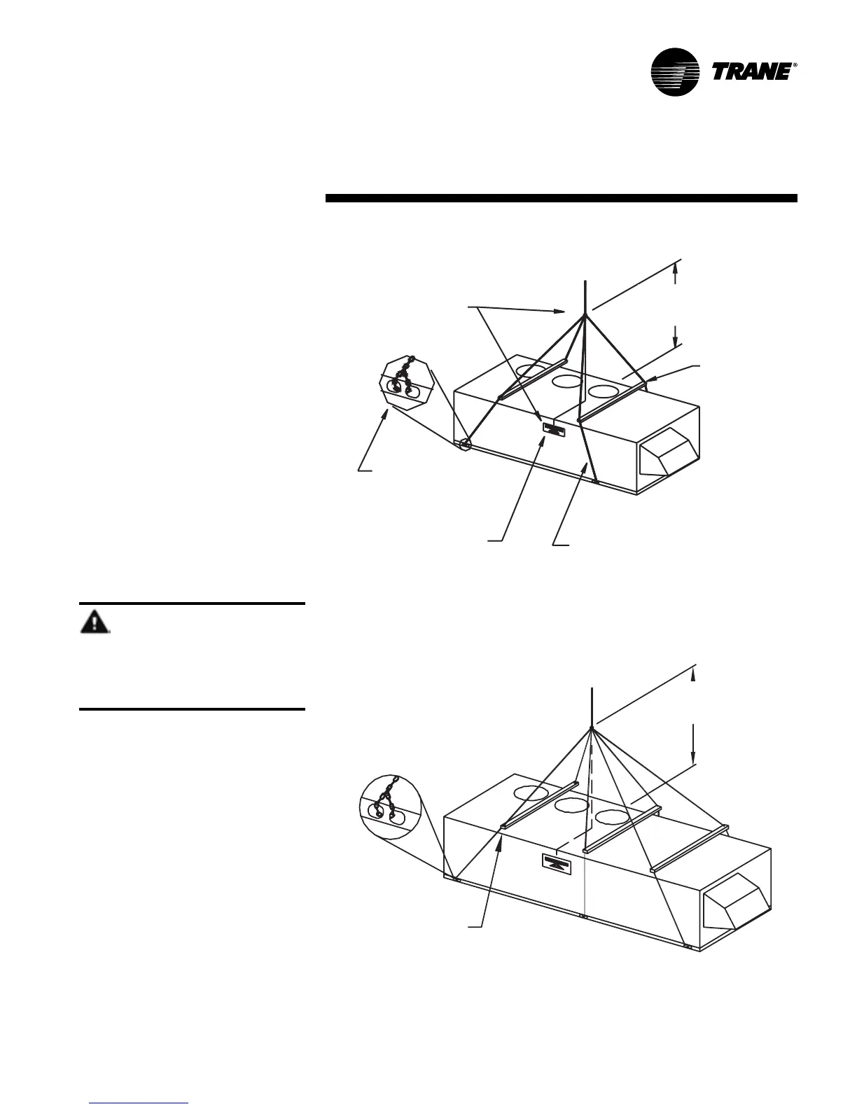
Figure I-IP-2. Proper fresh air unit rigging and handling for units without the total
energy wheel option
Rigging Procedure
1. Use spreader bars as shown in Figures
I-IP-2 and I-IP-3 to prevent upper cabinet
damage. If possible, use chains or
cables at lifting locations. Do not use
lifting hooks or chain hooks. Ensure
dimension A is not shorter than
recommended to prevent lifting
instability.
2. Cables used to lift the unit must be
capable of supporting the entire unit
weight.
3. Unit center of gravity (balance) is
located approximately at the position of
the center of balance labels along the
length of the unit. Also, you may
reference the center of gravity
locations in Figure I-IP-1 on page 40.
Leveling the Unit
The unit must be installed level to ensure
proper unit operation. The unit must be
level in both horizontal axis (max slope =
1
/
4
” per foot).
WARNING
Improper unit lift!
Failure to properly lift unit can cause
death, serious injury, or equipment/
property-only damage.
B
A
LIFTING POINT A MUST BE
ALIGNED DIRECTLY OVER UNIT
CENER OF BALANCE FOR A
LEVEL LIFT
7 FT. MINIMUM:
SHORTER LENGTHS
MAY RESULT IN LESS
LIFTING STABILITY
USE SPREADER BARS
EACH OF THE CABLES USED TO LIFT
THE UNIT MUST BE CAPABLE OF
SUPPORTING THE ENTIRE UNIT WEIGHT
LOCATION OF CENTER OF
BALANCE LABELS INDICATE
APPROX. CENTER OF BALANCE
LOCATION ALONG THE LENGTH
OF THE UNIT
USE CHAINS OR CABLES
DO NOT USE HOOKS IN
LIFTING HOLES
7 FT. MINIMUM:
SHORTER LENGTHS MAY
CAUSE LIFTING INSTABILITY
B
8 FT. MINIMUM
A
8 FT. MINIMUM:
SHORTER LENGTHS MAY CAUSE
LIFTING INSTABILITY
Figure I-IP-3. Proper fresh air unit rigging and handling for units with the total energy
wheel option
A
B
USE CHAINS OR CABLES. DO NOT
USE HOOKS IN LIFTING HOLES.
LABELS INDICATE APPROX.
CENTER OF BALANCE LOCATION
ALONG THE LENGTH OF THE UNIT
LIFTING POINT A MUST BE
ALIGNED DIRECTLY OVER
UNIT CENTER OF BALANCE
FOR A LEVEL LIFT