FAXA-SVX01B-EN 75
Maintenance
maintenance
procedures
Total Energy Wheel
Protect the total energy wheel by using a
30% filter to keep dust and dirt from the
heat transfer surface. The wheel is
somewhat self cleaning through its
normal action of rotating in and out of
counter-current airflow streams. If the
wheel becomes dirty, clean it by blowing
out the unit with compressed air, 20 psig
maximum.
Cleaning the Total Energy Wheel
Trane total energy wheels are self-
cleaning with respect to dry particles.
Smaller particles pass through the wheel.
Larger particles land on the surface and
are blown clear as the wheel turns into
the opposite airflow path. For this reason,
the primary cleaning required for the
total energy wheel is to remove the oil-
based aerosol film that collect on the
surface. Such films can close off micron-
sized pores at the surface of the desiccant
material, reducing its ability to absorb and
desorb moisture. Periodically record the
air temperatures entering and leaving
the energy wheel to detect changes in
performance.
In a reasonably clean indoor environ-
ment, such as a school or office building,
experience shows that reductions of
airflow or loss of sensible effectiveness
may not occur for ten or more years.
Where there is moderate tobacco smoke
or within cooking facilities, reduction in
effectiveness can occur much faster. In
applications experiencing high levels of
smoke, the energy transfer surfaces may
require cleaning as often as every six
months. Similar washing cycles may also
be appropriate for industrial applications,
such as welding or machining operations,
involving ventilation of high levels of
smoke or oil-based aerosols.
Proper cleaning of the energy wheel
should restore latent effectiveness to
near original performance.
Clean the total energy wheel as neces-
sary to maintain optimum airflow. When
washing/cleaning the wheel, take care
not to allow water or detergent to come
into contact with any of the electrical
components. Drain holes in the wheel
rack are capped and can be removed
during cleaning. Replace caps to avoid air
bypass. The single draw hole located
upstream of the outside air filters should
be utilized for draining, during cleaning.
Ensure no water, moisture, or excess
detergent is left in the energy wheel
compartment. Use a wet-vac vauum
cleaner to remove water/moisture as
needed.
Air Filter Replacement
Filter access doors are on both sides of
the unit. To replace filters, remove the
dirty elements and install new filters
(ASHRAE 30% or higher) with the filter
directional arrows pointing toward the
fan. Verify that no air bypasses the filters.
Inspecting and Cleaning the Drain Pan
Check the condensate drain pan and
drain line to ensure that the condensate
drains properly at least every six months
or as dictated by operating experience.
If evidence of standing water or conden-
sate overflow exists, take steps to identify
and remedy the cause immediately.
Refer to the trouble shooting section of
this manual for possible causes and
solutions. If microbial growth is evident in
the drain pan, remove and clean it
immediately. Clean drain pans using the
following procedure:
1. Disconnect all electrical power to the
unit.
2. Don the appropriate personal
protective equipment (PPE).
3. Remove all standing water.
4. Use a plastic scraper or other tools to
remove any solid matter. Remove solid
matter with a vacuum device that
utilizes high efficiency particulate
arrestance (HEPA) filters with a
minimum efficiency of 99.97% at 0.3
micron particle size.
5. Thoroughly clean the contaminated
area(s) with an EPA-approved sanitizer
specifically designed for HVAC use.
Carefully follow the sanitizer
manufacturer’s instructions regarding
product use.
6. Immediately rinse the drain pan
thoroughly with fresh water to prevent
potential corrosion from the cleaning
solution.
7. Allow the unit to dry thoroughly before
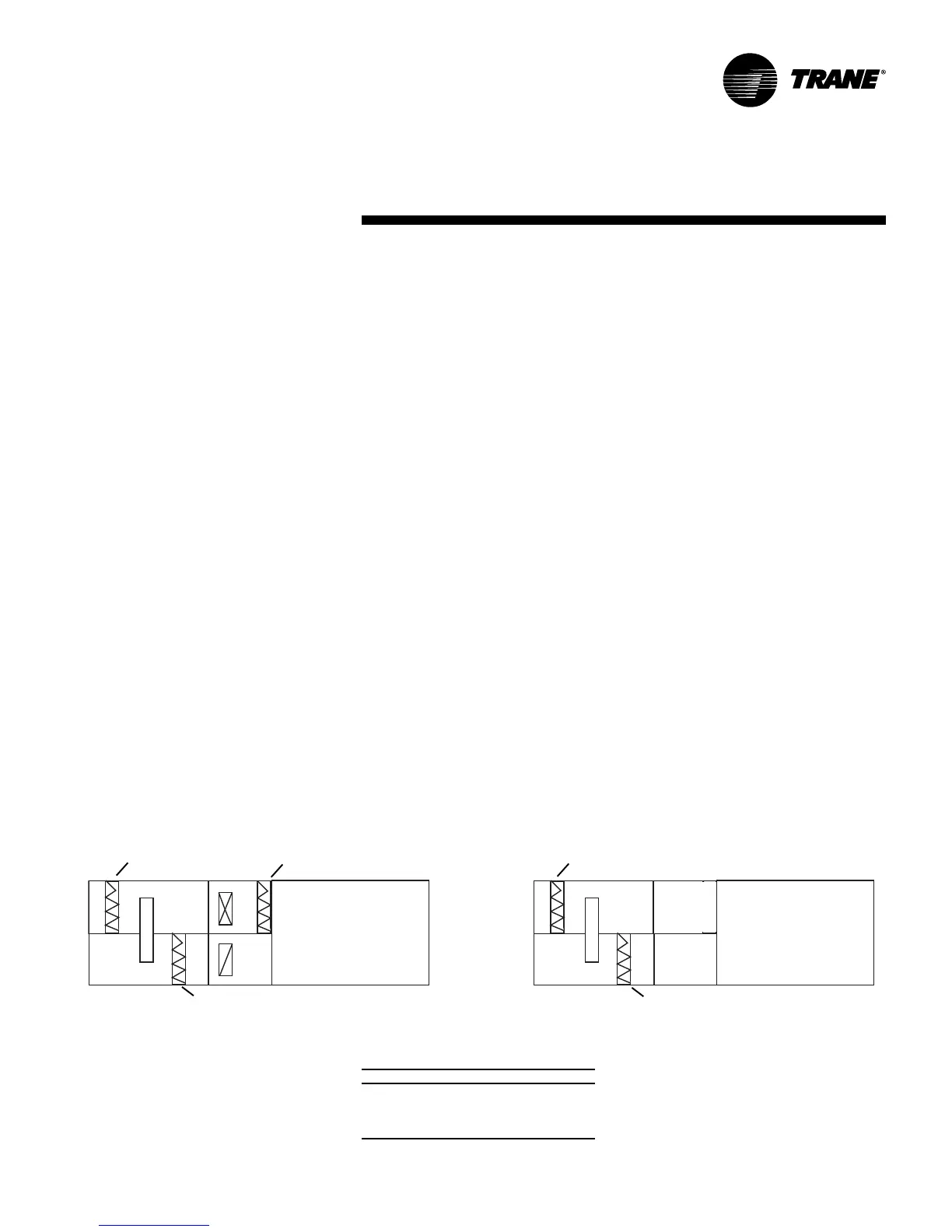
Figure M-MP-1. Filter placement three racks
with return
Figure M-MP-2. Filter placement two racks
without return
Table M-MP-1. Filter sizes, in.
unit size OA EA main unit
031 20 x 16 20 x 16 20 x 16
040 20 x 16 20 x 16 20 x 16
051 25 x 20 25 x 16 24 x 24
066 25 x 20 20 x 16 20 x 16
Note: Filters are ASHRAE 30% or higher.
OA
OA
EA
EA
UNIT
FILTER