WSHP-PRC004-EN18
Deluxe 24V
Controls
Features and
Benefits
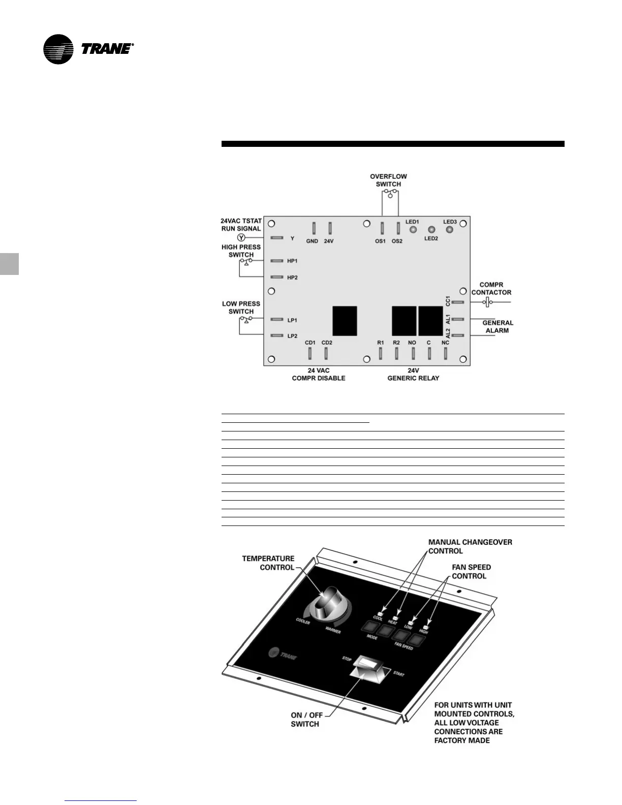
Microprocessor Board
The application drawing in Figure FB-32
references component device
connections to the microprocessor
board.
Three LED’s (light emitting diodes) are
provided for indicating the operating
mode of the controller. The LED’s are
intended
to aid in troubleshooting and unit
maintenance. The LED’s are labeled on
the circuit board with numbers as
referenced in Table FB-4.
Table FB-4 – Diagnostic LED’s
Color: Green Color: Red
LED1 LED2 LED3 Controller Mode
OFF OFF OFF Control OFF
ON OFF OFF Normal/Compressor OFF
ON OFF FLASH Anti-short cycle
ON OFF ON Normal/Compressor ON
FLASH ON OFF Brownout Condition
ON FLASH ON Soft Lockout (low pressure)
ON FLASH FLASH Soft Lockout (high pressure)
ON ON ON Manual Lockout (low pressure)
ON ON FLASH Manual Lockout (high pressure)
ON FLASH OFF Manual Lockout (condensate overflow)
ON ON OFF Compressor Disable
Figure FB-32 – Microprocessor Board
Unit Mounted Controls
Unit mounted controls are available with
both the basic 24 volt electronic control
package and the deluxe 24 volt
electronic control package. With the unit
mounted option, the low voltage wiring
for the unit is factory made.
Controls for the unit mounted package
include a cooler/warmer temperature
control dial, START/STOP manual power
switch, manual changeover from HEAT
to COOL, and fan speed control. See
Figure FB-33 for unit mounted 24 volt
controls.
Figure FB-33 – Unit Mounted 24 Volt Controls