10 SCXF-SVX01B-EN
The compressor, condenser, and fan
motor access panels are secured with
quick acting fasteners. Fast thread
screws secure access panels for
economizer coils, evaporator coils
expansion valves, water valves, and left
fan bearing. Access to other components
requires removal of semipermanent
panels secured with sheet metal screws.
During operation, sight glasses are
viewable through the portholes on the
unit’s left upper panel.
Disconnect electrical power
source before servicing the unit.
Failure to do so may result in
injury or death from electrical
shock or entanglement in moving
parts.
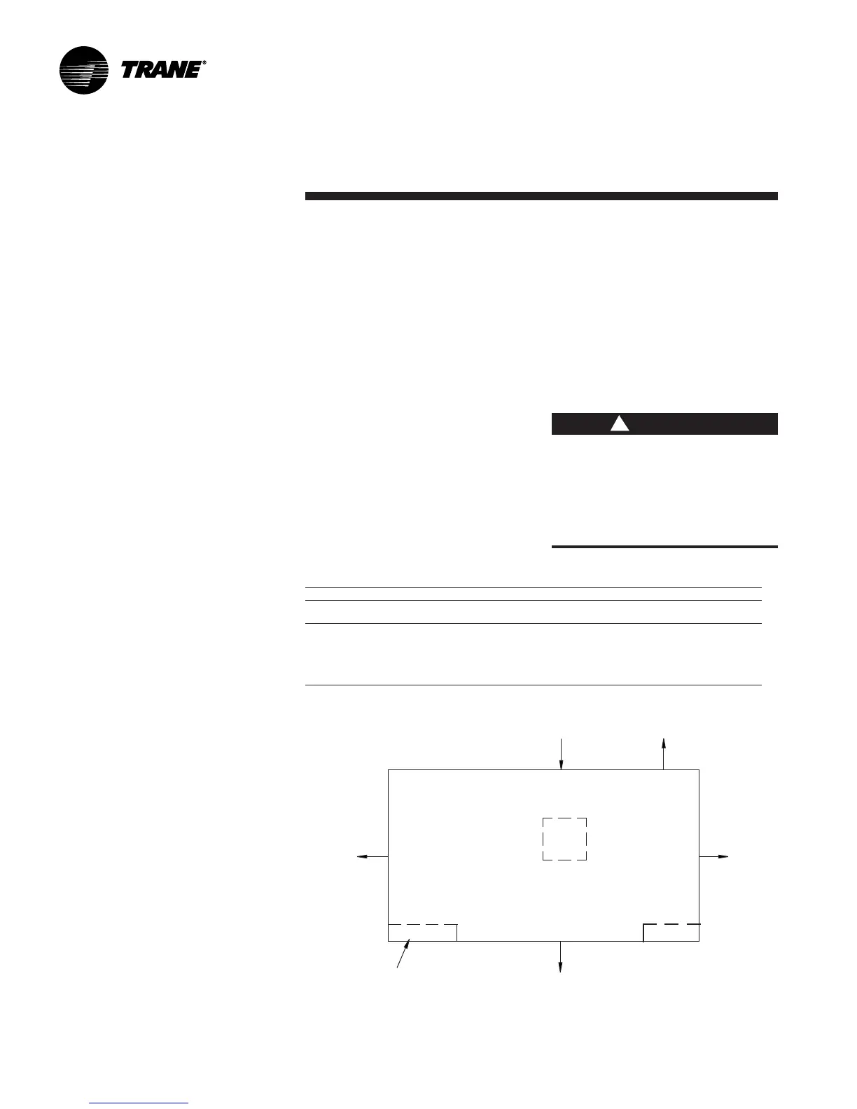
Table I-PC-1. Service and Code Clearance Requirements
Side Distance Purpose
Front 42 in. (1066 mm) (20-38 Ton) NEC code requirement
48 in. (1219 mm) (42-80 Ton) Fan service/removal
Left 36 in. (914 mm) Refrigeration and waterside component service
Right 9 in. (229 mm) Non VFD w/ open return
18 in. (457 mm) Non VFD w/ ducted return
24 in. (610 mm) w/ VFD 7.5 to 20 HP
36 in. (914 mm) w/ VFD 25 to 50 HP
Inlet 18 in. (457 mm) Provides uniform airflow
Service Access
See Figure I-PC-2 for recommended
service and code clearances. Access unit
controls through the front, top left panel.
The panel requires a screwdriver to
remove since it is secured with two quick
acting fasteners and an automatic latch.
Removable unit panels on the right-hand
side provide access to compressors, fan,
motor belts, extended grease line fittings,
drive side bearing, and inlet guide vanes.
On the unit’s left side, removable panels
allow access to the expansion valves,
filter driers, refrigerant sight glasses,
liquid line valves, opposite drive fan
bearing, inlet guide vanes, inlet guide
vane actuator, extended grease line
fittings, condensers, and waterside
economizer control valve.
WARNING
!
Figure I-PC-2. Top view of self-contained unit showing recommended service and code
clearances.
Air
Inlet
18” (457.2mm)
Minimum
See
Table
PC-1
Control
Panel
42” (1066.8 mm) (20-38 Ton)
Minimum
48” (1219 mm) (42-80 Ton)
Pre-Installation
Considerations
36” (914.4 mm)
Minimum
Installation
VFD

 Loading...


