10
S9V2-VS-SVX001-1D-EN
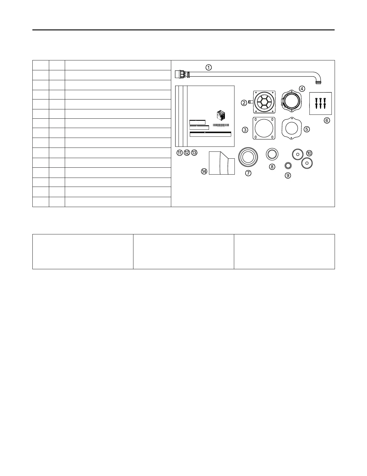
Document Pack Contents S9V2-VS
Item
Qty. Description
SSAAFFEETTYY WWAARRNN IINNGG
Onlyqualied personnelshould installand servicethe equipment.Theinstallation, startingup, andservicing ofheating, ventilating,and air-conditioning
equipmentcan behazardous andrequires specicknowledge andtraining.Improperly installed,adjusted oralteredequipment byan unqualiedperson
couldresultin deathorseriousinjury.Whenworkingon theequipment,observeallprecautionsin theliteratureandon thetags,stickers,andlabelsthat
areattachedtothe equipment.
Upow/Horizontal and Dedicated Downow
Gas-Fired, Direct/Non-Direct Vent, 2-Stage
Condensing Variab
l
e Speed Furnac
e
s with Variab
l
e Speed
Graphics in this document are for representation
only. Actual model may differ in appearance.
Note:
CAUTION
!
Failure to follow this Caution could result in property damage or personal injury. 4GXC* and
4MXC* coils installed on upflow furnaces in vertical, horizontal left, or horizontal right
orientations without a factory installed metal drain pan shield must use a MAY*FERCOLKITAA
kit. Coils installed on upflow furnaces must have drain pans that are suitable for 400° F
(205°C) or have a metal drain pan shield. Downflow furnaces do not require a metal drain pan
shield or the use of the MAY*FERCOLKITAA kit.
COIL REQUIREMENT!
Installation, Operation, and Maintenance
Draft Inducer
WARNING
FIRE HAZARD!
Failure to follow this Warning could result in property damage, severe personal
injury, or death.
This Warning applies to installations with a
ammable refrigeration system.
The furnace must be powered except for service. The furnace shall be installed
and connected according to installation instructions and wiring diagrams that
are provided with the evaporator coil.
July
2024
UUppffllooww,,CCoonnvveerrttiibbllee ttoo
HHoorriizzoonnttaall RRiigghhtt oorr
HHoorriizzoonnttaall LLeefftt
S9V2B040U3VSBB
S9V2B060U4VSBB
S9V2B080U4VSBB
S9V2C080U5VSBB
S9V2C100U5VSBB
S9V2D120U5VSBB
DDoowwnnffllooww OOnnllyy
S9V2B040D3VSBB
S9V2B060D3VSBB
S9V2B080D4VSBB
S9V2C100D5VSBB
S9V2D120D5VSBB
SS99VV22--VVSS--SSVVXX000011--11DD--EENN
1 1
Condensate Drain Tube Assembly
2 1
Inlet Vent (2”- ADP01586 and 3” - ADP01587)
(a)
3 1 Inlet Vent Gasket
4 1
Outlet Vent Assembly
5 1 Outlet Vent Gasket
6 6 Screws
7 1
Condensate Trap Grommet
8 1
Plug – Condensate/Gas
9 1
Plug – Electrical
10 2
Grommet – Condensate/Gas
11 1
Installation, Operation, and Maintenance
12 1 Owner Guide
13 1
Limited Warranty
14 1
2” to 3” Coupling – CPL01544
(b)
(a)
3” inlet vent supplied with S9V2D120U5VS only. 2” inlet vent supplied with all other models.
(b)
Supplied with S9V2D120U5VS only.
Part List
• Igniter
• Flame Sensor
• In-shot Burner(s)
• Gas Valve
• Inducer Assembly
• Blower Motor
• Blower Wheel
• IFC (Integrated Furnace Control)
• Pressure Switch(es)
• Main Thermal Limit
• Roll-Out Switch(es)
• Reverse Air Switch(es)
AAcccceessssoorriieess