Act
i
ve
Erro
rs
Example
1
s
t
stage Gas Heat
Example
800 CFM
Example
2
nd
Stage Pressure
Switch Error
Example
1st Stage Pres
sure
Switch Error
Last 6 Faults
Example
2
nd
Stage Pressure
Switch Error
Example
1st Stage Pressure
Switch Error
Example
Open Limit Switch
Erro
r
Control Release#
Example
Software Version #
Cooling Off Delay
Example
seconds
Example
Enhanced Mode
OD Tonnage
Exa
mpl
e
Outdoor Nominal Tonnage
OD Unit Type
Example
Con!
nu
ous
F
an
Example
50% Cooling
Ai
rf
l
o
w
Cooling C
FM
Example
CFM per Ton
Example
Seconds
In
ter-
Stage Delay
Exam
ple
Se
c
o
nds
Gas Heating CFM
Exa
mpl
e
2
nd
stage Hea
ting CFM
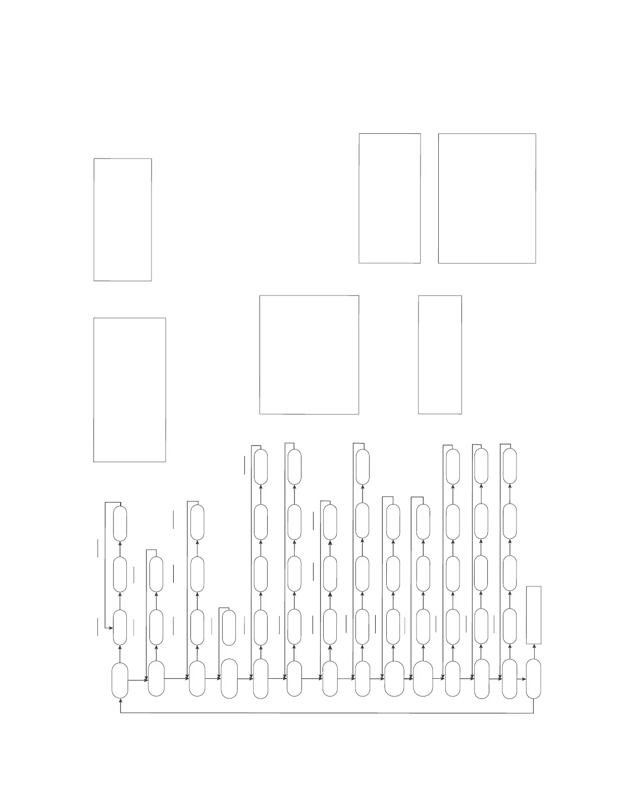
S
9V2-VS
Control System Menu
Example
2 stage 1 compressor
Example
2 stage
2
co
mp
resso
r
CLEARING THE LAST6 FAULTS:
To clear
the stored faults,
scroll to the last 6 fault
menu (L6F), enter the menu by
s
c
rolling to the right
and hold the “OPTION” k
e
y
for at least 5 seconds.
Rele
a
s
e and a set of 3 dashes will be seen 3 times.
This confirms the faults have b
een cleared.
SETTIN
G UP
Y
OUR SYSTEM:
T
o change any factory default value, first remo
ve any “call”
from the furnace and allow any fan off delays
to finish. (
should be seen on t
h
e di
sp
l
ay.)
Scroll to the selected Menu
item by momentarily depressing
the “MENU” key and
t
h
en
depress the “OPTION” key to the
de
si
r
ed setting. Then momentarily depress
t
he “M
ENU” key
again to save the ch
a
nge.
CFM per Ton selections range from 2
90
– 450
Imp
o
r
t
an
t:
When applied with
zo
n
ing or a VSPD outdoor unit,
the CFM/T
o
n
must be set to 400.
Gas Heating CFM shown is 2
nd
stag
e
a
i
rf
l
ow. 1
st
stage
airflow is ~80% of the selected 2
nd
stage a
i
rf
low and
cannot be adjusted.
Gas heatin
g CFM can be adjusted while the unit is
operating in gas heat mode to
enable the technician to
quickly adjust to the m
anufacturer's suggested heat
rise
a
cr
oss the heat exchanger.
Multiply
the value shown by 10 for actua
l
airflow.
Model Gas Heating CFM [ ]=Default
Upflow
S9V2B060U4VS 116[116], 1
3
0
,
099,
109
S9V2B080U4VS 126[126], 133,
146, 120
S9V
2C100
U
5VS 183 [183], 145, 162, 172
S9V2D120U
5VS 195 [195], 225, 156, 185
Downflow
S9V
2
B
0
8
0D4VS 133 [133], 148, 1
20, 126
S9V2C100D5VS 18
7
[18
7], 210, 152, 180
Model
O
DT Options [ ]= Default
Upflow
S9V2
B040U3VS 3T[3T], 1.5T, 2T, 2.5T
S9V2B060U4VS 4T[4T], 2T, 2.
5
T
, 3T
S9V2B080U4VS 4T[4T],
2T, 2.5T, 3T
S9V2C
100U5VS 5T[5T], 3T, 3.5T,4T
S9V2D120U5VS 5T[5T], 3T, 3.5T, 4
T
Downflow
S9V2
B080D4VS 4T[4T], 2T, 2.5T, 3T
S9
V2C100D5VS 5T[4T], 3T, 3.5T, 4T
Heatin
g
C
FM
p
er Ton
per Ton
Exam
ple
CFM per Ton
Run Test Mode
See Run Test M
enu
1 stage 1 compressor
50
75
100
25
370
400
370
350
35
0
100
600
400
180
900
000
300
116
130
099
109
Note:
Do not adjust COF above 50%.
S9V2B040U3VS 088 [088], 120, 065,
083
S9V2B060D3VS 103[103], 113, 135, 090
S9V2B060D3VS 3T[3
T]
,
1.5T, 2T, 2.5T
S9V2C080U5VS
5T[5T], 3T, 3.5T,4T
S9V2B040D3VS
3
T
[3
T],
1.5T
,
2T, 2.5T
S9V2D120D5VS 5T[4T], 3T, 3
.5T, 4T
S9V2C080U5VS
145[145], 156, 170, 119
S9V2B040D3VS 082[082], 095, 125, 065
S9V2D120D5VS 225[225],175, 185,195
L
Status Menu
I
d
L
I
d
HT1 ARF
080
ERR
E3_4
E3_4
E3_1
E3_1
L6F
E04
021
000
COd
Odt
ODU
COF
CpC
CpH
HOd
9HC
15d
rUn
3_0 1_5
1_1 2_1 2-2
2_0 2_5
090 180 EH
CR
Heat Off Delay
140
60