S9V2-VS
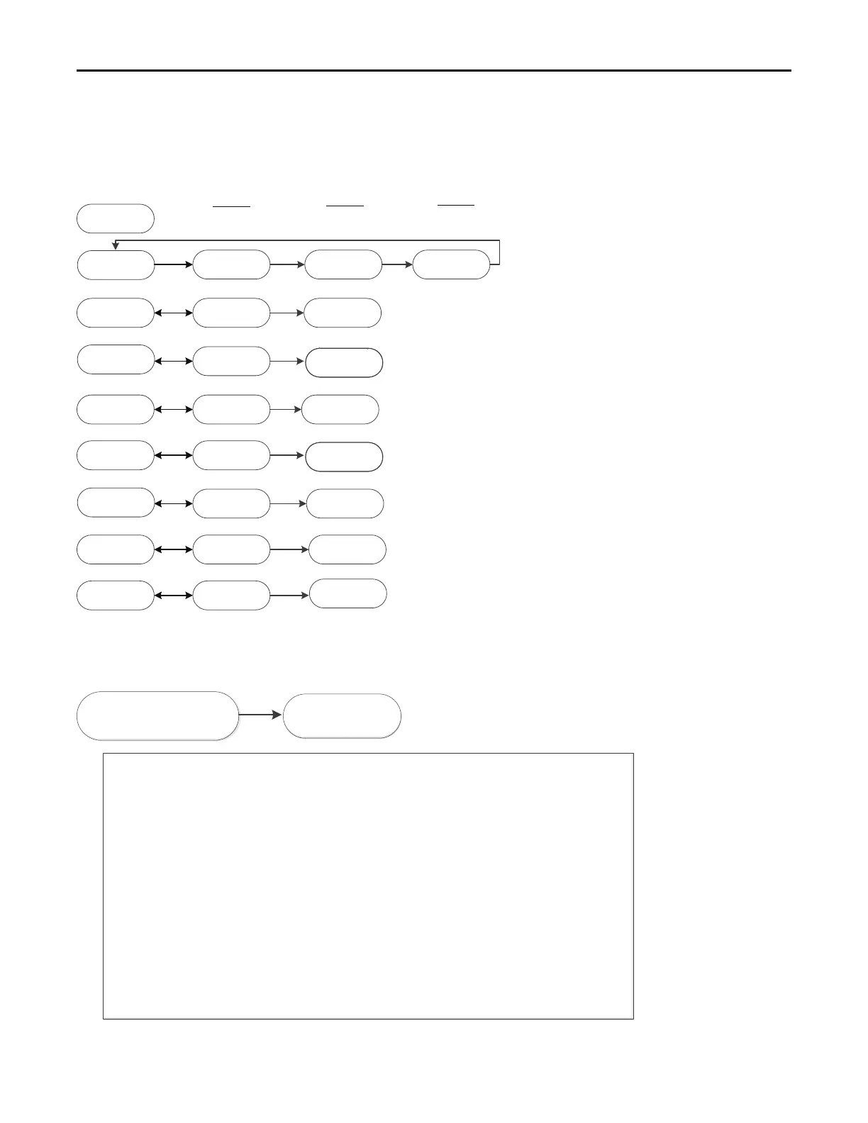
Examples of System Status
= Idle, no demand for cooling, hea!ng, or fan
= Demand for 1
st
stage gas heat
= Demand for 2
nd
stage gas heat
= Demand for 1
st
stage cooling
= Demand for 2
nd
stage cooling
= Demand for 1
st
st
stage heat pump
= Demand for 2
nd
stage heat pump
= Demand for con!nuous fan
= Demand for outdoor unit defrost, furnace running in gas heat mode
Calculated airflow is 800 CFM.
Airflow display is rounded down to the nearest 10 cfm
NOTES:
(1) The menu status displayed is solely dependent on the input of 24VAC
that is applied to the low voltage terminal strip.
(2) The status will alternate between the system mode and the airflow
request every 2 seconds.
(3) If an error occurs, an E*.* will alternately flash with the system mode
and airflow request. See first example
(4)
Mul!ply the value shown by 10 for actual airflow
Example
800 CFM
Example
1st Stage Pressure
Switch Error
Example
Calculated Airflow
= 1 stage gas heat learning rou!ne
1 dL
080
E3_1
Ht2 130
CL1
CL2
080
140
HP1
HP2
080
140
C0F
DFT
ArF
ArF
080
140
HT1
1 dL
HT1
Ht2
CL1
CL2
HP1
C0F
DFT
ArF/080
HP2
ArF
ArF
ArF
ArF
ArF
ArF
LR1
nd
= 2 stage gas heat learning rou!ne
LR2
Run Test Mode
Run Test Mode:
To enter Run Test Mode, scroll to using the Menu key, then push the op!on key. The LED will flash three
!mes, then begin the test.
To exit the test mode, momentarily push the Menu key, cycle power to the furnace, or make a valid thermostat
call for capacity or fan.
Sequence of Run Test Mode
– Turns the inducer on in 1
st
stage for 30 seconds
– Turns on the inducer on 2
nd
stage for 30 seconds
– Turns the ignitor on for 10 seconds
– Turns the circula!ng blower on 1st stage compressor speed for 10 seconds
– Turns the circula!ng blower on 2nd stage compressor speed for 10 seconds
– Turns the circula!ng blower on 1
st
stage gas heat speed for 10 seconds
– Turns on the circula!ng blower on 2
nd
stage gas heat speed for 10 seconds
The above sequence will repeat two more !mes unless the Run Test Mode is exited, see above
Important: The Run Test Mode does not test fire the furnace or bring the outdoor unit on. It is designed to allow
the technician to observe each mode to ensure the IFC, inducer, and circula!ng blower are performing as
intended.
Note: During run test mode, depressing the option key will allow the user to hold (HLD) that test
sequence if measurements want to be taken. The exception is RU3 (ignitor).
run
ru1 - ru7
run
run
ru1
ru2
ru3
ru4
ru5
ru6
ru7