22 CTV-PRB004-EN
Low-Voltage Starter Types
Low Voltage—Solid-State
Solid-State Starters
TheTrane
®
solid-state starter produces a soft start with a gradual inrush current and no transition
spikes. It controls the starting characteristics of a motor by controlling the voltage to the motor. It
does so through the use of silicon controlled rectifiers (SCRs), which are solid-state switching
devices, and an integral bypass contactor for power control. An SCR will conduct current in one
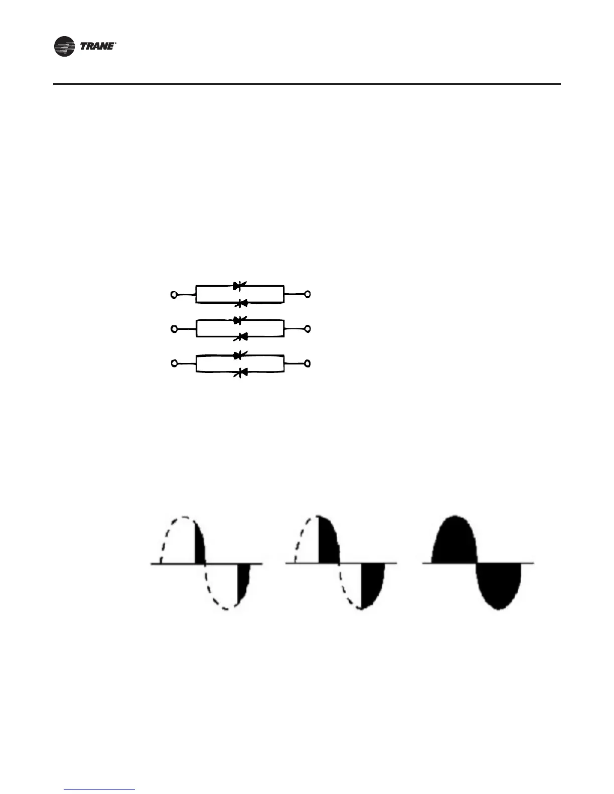
direction only when a control signal (gate signal) is applied. Because solid-state starters use
alternating current (AC), two SCRs per phase are connected in parallel, opposing each other so that
current may flow in both directions. For three-phase loads, a full six-SCR configuration is used, as
shown in Figure 13.
Starting sequence
During starting, control of current or acceleration time is achieved by gating the SCRs “on” at
different times within the half-cycle.The gate pulses are originally applied late in the half-cycle and
then gradually applied sooner in the half-cycle. If the gate pulse is applied late in the cycle, only a
small increment of the wave form is passed through, and the output is low. If the gate pulse is
applied sooner in the cycle, a greater increment of the wave form is passed through, and the output
is increased. By controlling the SCRs’ output voltage, the motor’s acceleration characteristic and
current inrush are controlled as illustrated in Figure 14.
When the SCRs are fully “phased on,” the integral bypass contactors are energized.The current
flow is transferred from the power pole to the contactors.This reduces the energy loss associated
with the power pole, and extends contactor life. When the starter is given the stop command, the
SCRs are gated “full voltage” and the bypass contactor is de-energized.The current flow is
transferred from the contactors back to the power poles. Less than one second later, the SCRs are
turned off and the current flow stops.
Figure 13. Six-SCR arrangement
Figure 14. Starting sequence wave forms
L1
L2
L3
T3
T2
T1
25% voltage 50% voltage full voltage
CTV-PRB004.book Page 22 Sunday, December 18, 2011 6:39 PM