70 CTV-PRB004-EN
Starter Options
PFCC Placement and Sizing. PFCCs may be installed at various locations in the power supply
network. Utility companies install capacitor banks on their distribution feeders and substation
buses.These capacitors correct for the utility’s reactive loads and for other large reactive loads,
such as those found in business or industrial areas.
When utility customers correct for the reactive loads in their facilities, they usually install PFCCs
at the facility’s electrical service entrance or at the individual loads within the facility. Connecting
the PFCCs at the service entrance corrects reactive loads throughout the facility.This strategy can
be advantageous if the facility contains a large number of small reactive loads—but it can also be
costly. Successful implementation requires expensive hardware to monitor the power factor as
loads are added to and removed from the distribution system, then switch capacitors on- and
offline accordingly.To avoid this expense, PFCCs are most commonly installed near each piece of
switchgear that supplies a reactive load.
Engineering Toolbox. Trane has a program called EngineeringToolbox, available online or
throughTrane Desktop Manager, that can be used to calculate the kilovolt-amperes reactive (kVAR)
of correction needed. Toolbox can calculate kVAR using information from the motor data sheets
without adjustments at 60 and 50 Hz. Contact yourTrane sales representative for more information.
PFCC Application Guidelines. Three “rules” govern the application of capacitors dedicated to
a specific reactive load and its switchgear:
• “Rule 1”—Simultaneously disconnect capacitors and load from line power
• “Rule 2”—Size motor overload protection to account for capacitor-supplied current
• “Rule 3”—Accurately size PFCCs that remain connected to the motor when it is offline
These guidelines are explained on the following pages.
Rule 1—Simultaneously disconnect capacitors and load from line power.
If the capacitors are not switched offline when the load is disconnected, they continue to add
capacitance to the electrical distribution system. A “leading” power factor—too much capacitance
may eventually develop.This overcorrection causes poor voltage regulation, i.e., voltage is high
when the circuit is unloaded, then drops as loads are added.
Rule 2—Size motor overload protection to account for capacitor-supplied current.
Overloads are typically set to measure the total current drawn by the motor.When PFCCs are used,
they become another source for a part of that current. If the current they provide is not “seen” by
the overload protectors, potentially damaging amperage can reach the motor.The simplest way
to ensure that the overloads “see” all current supplied to the motor is to position the PFCCs
upstream of the overloads as shown in Figure 49.
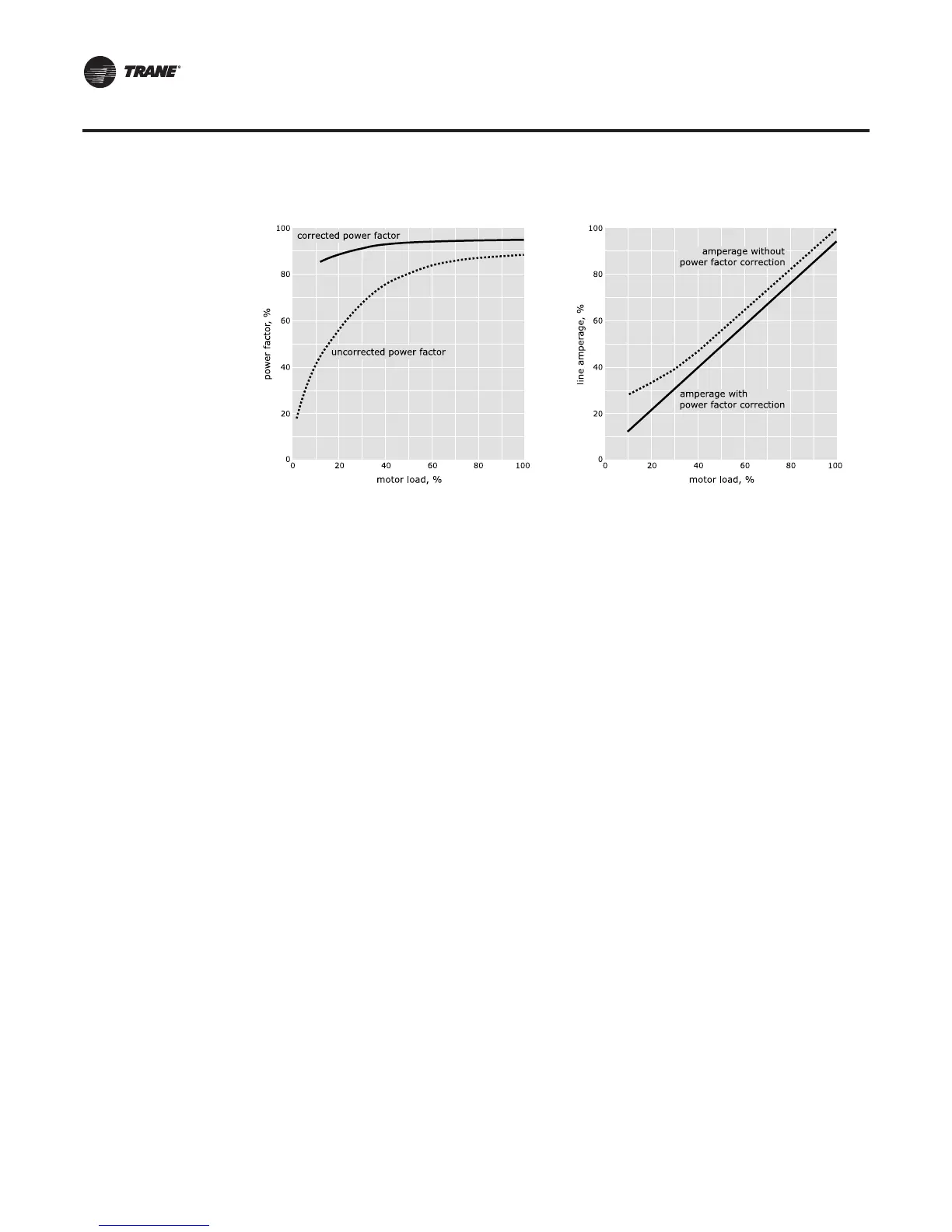
Figure 48. Typical CenTraVac chiller-motor power factor
CTV-PRB004.book Page 70 Sunday, December 18, 2011 6:39 PM