72 CTV-PRB004-EN
Starter Options
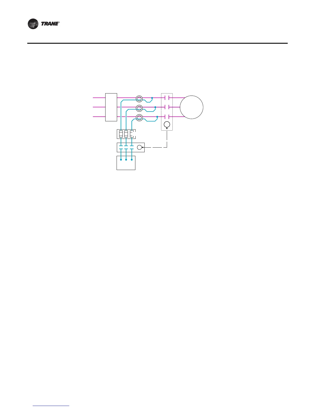
Line-side PFCC placement. Figure 51, depicts an arrangement that provides an alternative to
installing capacitors downstream of the motor-starter contactor. While this configuration can be
used with any type of starter, it is mandatory for all solid-state starters. Notice that the PFCCs are
connected to the line side of the main contactor (or other switching device) via a separately
controlled contactor.This separate contactor is governed by a pilot relay (PR) at/in the motor-starter
contactor or silicon controlled rectifiers (SCRs, solid-state starter applications) to switch the
capacitors on- and offline with the load.
By connecting the PFCCs through a separate contactor they do not remain connected to the motor
or the line when the motor is disconnected.This configuration prevents voltage-feedback problems
and can be used for cases where correction beyond 95 percent is desirable. Correction beyond the
manufacturer’s maximum limit should not be done without consulting the manufacturer regarding
the application.
If the PFCC connections are downstream of the overloads, the capacitor leads must be routed
through the overloads as Figure 51, p. 72 illustrates. Notice that the capacitors are not connected
to the motor when it is disconnected from the line.This prevents the “motor-generated voltage
buildup” described in “Rule 3”, p. 71.
Figure 51. PFCCs with separately controlled motor contactor
Enclosed 3-Phase
Capacitor Unit
Motor
Power
Circuit
Fusible
Safety Switch
or
Suitable Breaker
Overload
Protectors
1
2
3
Motor Starter
Contactor
or
Silicon-Controlled
Rectifiers (SCRs)
Fuses
C
PR
CTV-PRB004.book Page 72 Sunday, December 18, 2011 6:39 PM