PKG-SVX029A-EN
7
Overview
Note: One copy of this document ships inside the control
panel of each unit and is customer property. It must
be retained by the unit maintenance personnel.
This manual describes proper installation, operation, and
maintenance procedures for water cooled systems. By
carefully reviewing the information within this manual and
following the instructions, the risk of improper operation
and/or component damage will be minimized. It is
important that periodic maintenance be performed to help
support trouble free operation. A maintenance schedule is
provided at the end of this manual. Should equipment
failure occur, contact a qualified service organization with
qualified, experienced HVAC technicians to properly
diagnose and repair this equipment.
R-454B Compressors
• Use crankcase heaters which must be energized 24
hours prior to compressor start.
Note: This unit is equipped with stator heating
capabilities that eliminates the need for a
crankcase heater on the variable speed
compressor only. All fixed speeds must utilize a
crankcase heater.
• Contains POE oil which readily absorbs potentially
damaging moisture from air.
• Control box includes a phase monitor to detect phase
loss, line voltage imbalance, and reversal.
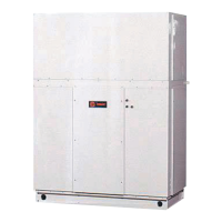
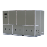
SWUD Components
SWUDs are complete HVAC systems used in floor-by-floor
applications.
• A single piece cabinet design to target new
constructions.
• Left hand power connections.
• Left or right hand water connections.
• Factory installed options.
The hermetically sealed scroll compressor motors utilize
internal motor protection and time delays to prevent
excessive cycling.
Units utilize two refrigerant circuits and ship with a R-454B
charge and full oil charge. Each circuit includes filter drier,
pressure relief valve, moisture indicating sight glass,
thermostatic expansion valve with sensing bulb and
externally equalized, and high pressure cutout. The water
cooled condensers are shell and tube. It is recommended
to clean the condenser mechanically, but the condenser
can be cleaned chemically.
Fan array consists of 1-7 direct drive plenum fans with
each fan equipped with ECM motors.
Figure 1. SWUD components
Standard Controls
Standard controls supplied with the unit include Symbio™
500 unit controls and the TD-7 touch screen display. All
basic setup parameters are preset from the factory.
TD-7 Touch Screen Display
• TD-7 is unit mounted and accessible without opening
the unit front panel.
• Use the TD-7 touch screen for easy setpoint
adjustment.
• The TD-7 displays all unit operating parameters and
conditions in a backlit color screen.
Symbio 500 Unit Controller
The Symbio™ 500 provides smart unit control with safety
features and control relays for external devices. The
Symbio 500 utilizes BACnet® MSTP to communicate to a
front end Building Automation System (BAS).
The SWUD self-contained unit is controlled by a
microelectronic programmable control system programmed
from the factory specifically for the application. If additional
input or output points are needed, expansion modules can
be used.
For more detailed information on the control points
provided, see the Owners section of this manual.
Optional Controls
Optional controls include a disconnect switch, dirty filter
switch, water flow switch, supply air temperature reset, or
external setpoint inputs. Morning warm-up operation is
available on all units with heat or with downstream VAV
boxes with heat.
Note: A water flow switch is required for the installation,
either supplied from the factory or field-provided.
The static pressure probe, supply air temperature reset
sensor options ship separate, but with the unit for field