BAS-SVX084A-EN 11
Overview
Device Inputs/Outputs
Below is a list of device inputs and outputs.
• A twisted/shielded communication link
• Zone sensor
• Occupancy sensor (optional)
• Discharge Air Temperature (DAT)
•CO
2
sensor
• 24 Vac, Class II power
Table 4 provides details for each type input/output.
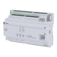
Table 4. Symbio
210 inputs and outputs
Analog Inputs 1 through 3
Note: Configuration options when used as spare; 10kthermistor, 0 to
1k
linear setpoint, 200 to 20k linear.
Universal Inputs UI1 and UI2
Note: Configuration options when used as spare; 4–20mA, 0-10V,
resistive (see AI specifications), binary (solid state open collector)
• AI1: Space temperature; thermistor: 10k
@77°F (25°C) range: 32°F
to 122°F (0°C to 50°C)
• AI2: Space setpoint; potentiometer: 1k
from 50 to 90°F (10 to
32.2°C), */** (thumbwheel) functionality supported
• AI3: Discharge air temperature: 10k
@77°F (25°C) from -40°F to
212°F (-40 to 100°C)
• UI1: Relative Humidity
• UI2: CO
2
Pressure Input P1 Binary Input BI1, Dry Contact
• P1: Supply air flow; pressure transducer: From 0 to 5 in. water column
(0 to 1245 Pa)
• BI1: Occupancy
Analog Outputs AO1 and AO2
Note: Configuration options when used a spare; Voltage output is 0 to 10
VDC, 500 ohm min. impedance. Current output is 4 - 20 mA, 500
max. impedance.
Binary Outputs 1 through 5
Note: 0.5A Resistive Maximum Rating
• AO1/B12: ECM
• AO2/B13: SCR Heat/Waver Valve Signal
• BO1: Heat stage 3 TRIAC
• BO2: Heat stage 2/Water Valve Close TRIAC
• BO3: Heat stage 1/Water Valve Open TRIAC
• BO4: Air Damper Open TRIAC
• BO5: Air Damper Close TRIAC

 Loading...