ACC-APG001A-EN
9
Table 1. Field Connections (continued)
Connector Function Pin #
Signal
J21 Thermostat Connections
1 24VAC
2 Y1
3
W1/O
4 G
5 W2
6 Y2
7 X2
8 1.5K Ohms Pull-down
9 GND
J22 CO
2
1 24Vdc Out
2 CO
2
In
3 Common
J23
Space Humidity
1 24Vdc Out
2
Space Humidity
3 Common
Unit Configuration
The Odyssey system can be configured via an onboard user interface or via the Symbio Service
and Installation mobile app.
Onboard User Interface
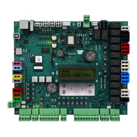
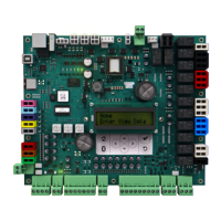
The onboard user interface provides a 2 x 16 Backlit LCD display and navigational buttons. This
allows the user to view status, configure, and troubleshoot the unit without additional tools.
Figure 2. Symbio 700 Onboard User Interface
The interface provides an intuitive menu structure: alarms, status, service, settings, and utilities.
Configuration of the unit is accomplished under the utilities menu item. A complete list of
functions is outlined in the Symbio 700 User Guide - BAS-SVU054.
SSyymmbbiioo 770000 OOvveerrvviieeww
 Loading...
