TK 55676-19-IM-EN
81
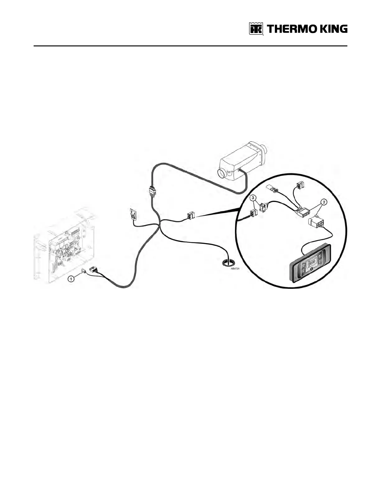
Connecting Diagnostic Tool
1. Connect only the 2-pin connector ((RReedd,, BBrroowwnn)) heater power wire (installed earlier in the control box) to mating
connector (J9) on the interface board.
NNoottee:: DDOO NNOOTT connect the 14-pin connector at this time. It will be connected after the Heater Start-Up Procedures have
been completed.
2. Connect the adapter harness to the Diagnostic Tool.
3. Connect the 8-pin diagnostic connector to the mating connector located on the heater harness inside the sleeper
near the heater.
NNoottee:: The two remaining adapter harness connectors shown in the illustration are not used.
Figure 46. Diagnostic Tool Connections to Heater
HHeeaatteerr SSttaarrtt--UUpp PPrroocceedduurreess