4 BAS-SVN026G-EN
Equipment/Software Supported
The zone sensor will work with Trane fan coil, blower coil, unit ventilator, and water source heat
pump equipment that uses the Trane UC400 control system.
Installation and Guidelines
• Do not install on an outside wall.
• Do not install in areas with direct heat source.
• Do not install near any air discharge grill.
• Do not install in areas exposed to direct sunlight.
• Ensure the sensor has sufficient air circulation.
• Ensure the mounting wall surface is flat and clean.
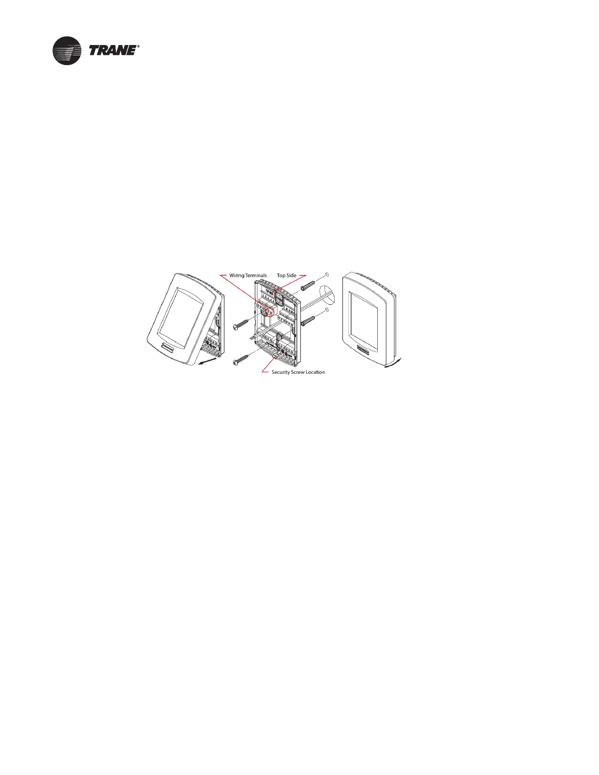
1. Remove the security screw from the bottom of the sensor (if present).
2. Firmly grasp the sensor and pul
l up on the bottom to remove the sensor from the baseplate.
3. Drill a 1.5-inch diameter hole in the wall
where the sensor will be located.
4. Feed the power/communication wires through the hole.
5. Strip the wire coating ends approximately .25 inch.
6. Loosely install an EMI choke on each wire as sh
own in the wiring diagrams.
Note: Wire must
make two complete wraps around each choke.
7. Feed the wires through the mi
ddle of the baseplate.
8. Insert the wires into the wire
terminals (per terminal identification in wiring diagrams) and
tighten down the terminal screws to secure the wires.
9. Slide each EMI choke along wires toward the bas
eplate until they are approximately a distance
of 2 inches.
Note: Gent
ly pull on both ends of each wire so they are snug around each choke.
10. Feed each wire/choke back i
nto the hole so the baseplate can be mounted flush to the wall.
11. Center the baseplate over the hole and ensuring
correct orientation.
Note: TOP i
s embossed on baseplate to indicate proper orientation.
12. Vertically align the baseplate and mark the top/bottom mounting hole locations on
the wall.
13. Install the provided wall anchors and affix the baseplate to wall with the wall anchors screws
.
14. Attach the sensor to the ba
seplate by aligning the tabs at the top edge of the sensor with the
notches at the top of the baseplate. Press down on the bottom half of the sensor to snap into
place. The device will power up after applying power.
15. Install the security screw on the bottom
of the sensor to avoid tampering.

 Loading...


