22 UV-SVP01A-EN
Mounting
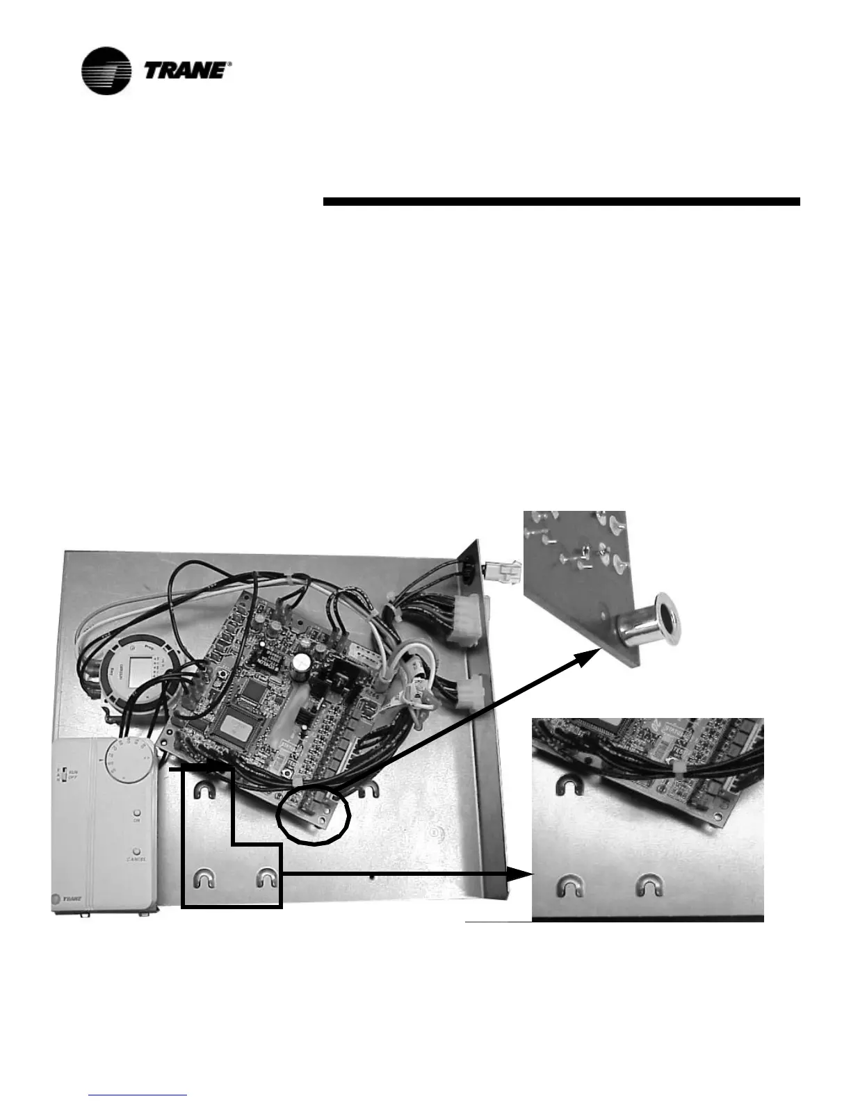
The Tracer ZN.520 circuit board is
mounted in the left-hand end pock-
et for all classroom unit ventilator
configurations. The sheet metal
mounting plate has raised emboss-
es to accept the mounting feet on
the circuit board. (See Figure 8:
“Classroom unit ventilator control
box with close-up of horseshoe
embosses and circuit board
mounting feet.”) This design al-
lows the Tracer ZN.520 controller
to be secured with a minimal num-
ber of sheet metal screws.
Figure 8: Classroom unit ventilator control box with close-up of horseshoe embosses and circuit board mounting feet.
Installation and Wiring

 Loading...


