PART-SVN121A-EN 15
Installation of TR200 VFD and Components
5. Hex nut ( .31-18 ST)
Control Wiring to TR200
Reconnect all control wires to the TR200 VFD according to the connection point numbers noted
during TR1 removal. The TR1 and TR200 have the same connection point numbers. See Ta b le 1 ,
p. 8 for common control wires and their connection point numbers. See Tab l e 2, p. 8 for VFD
keypad cables listed according to product line and function.
The existing unit VFD schematic may be used as a reference or specific wiring schematics can be
found in “Wiring Diagram Matrix,” p. 19.
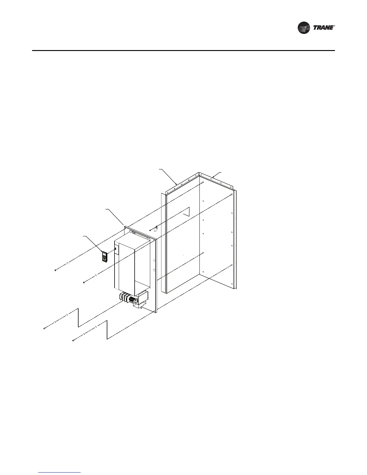
Figure 7. Typical VFD installation
VFD Keypad
VFD Enclosure
Back Panel
VFD Enclosure
Side Panel
Backpanel and TR200
Drive Assembly

 Loading...


