PART-SVN121A-EN 11
Installation of TR200 VFD and Components
VFD and Back Panel Assembly for TR200
WARNING
Heavy Objects!
Do not use cables (chains or slings) except as rated. Each of the cables (chains or slings) used to
lift the unit must be capable of supporting the entire weight of the unit. Lifting cables (chains or
slings) may not be of the same length. Adjust as necessary for even unit lift. Other lifting
arrangements may cause equipment or property-only damage. Failure to properly lift the unit
could result in death or serious injury. See details below.
Remove VFD TR200 from the box and find the adapter plate from the kit to follow the instructions
below.
TR200 Drive Installation instruction
1. Identify the hole-pattern on the TR200 adapter plate that matches the TR200 replacement drive.
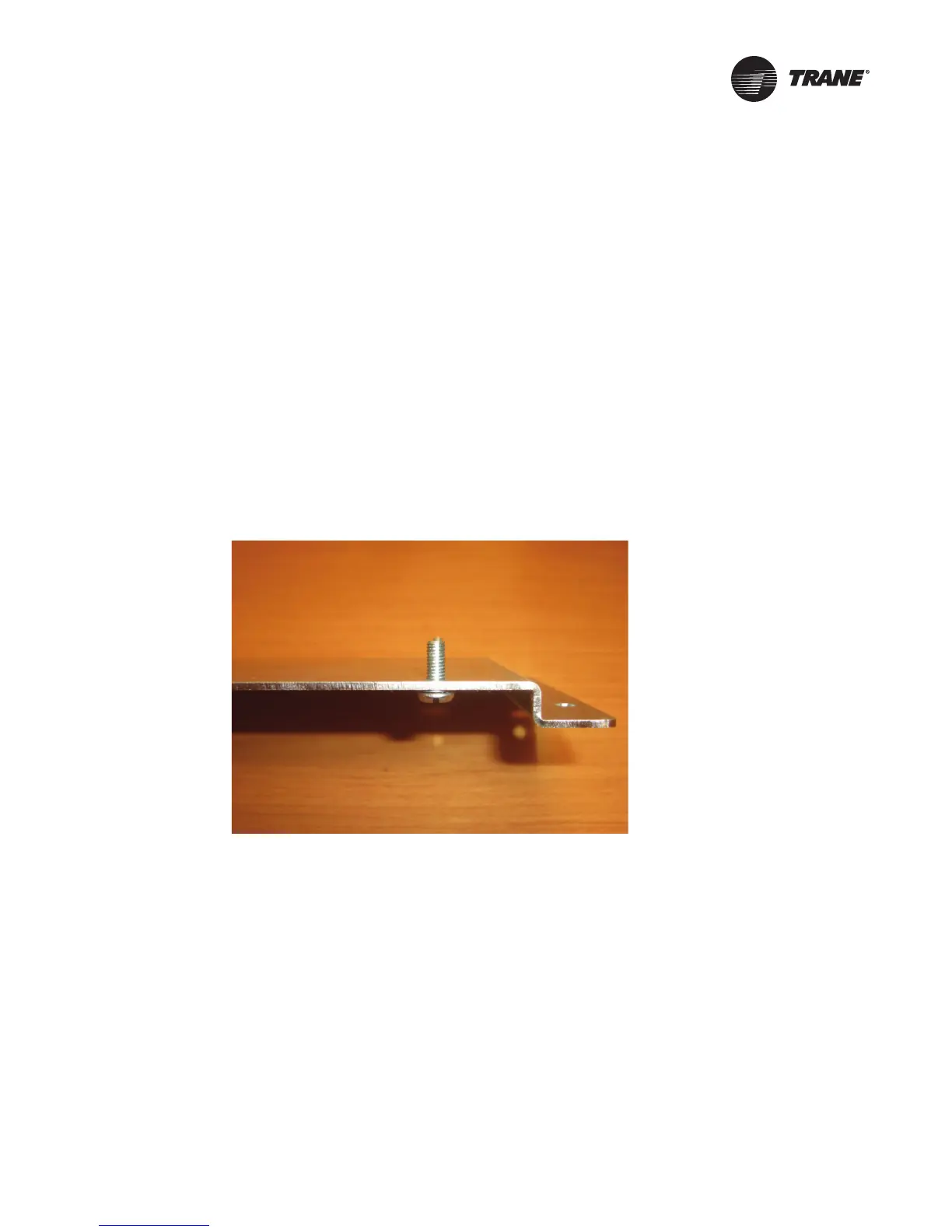
2. Install kit-supplied screws (SCRW MACH HEX .25-20x .625) and internal tooth lock-washers
(WASH LOCK SPL .25x.484x.072 ST) in the TR200 drive adapter plate from the back.
3. Line up the TR200 on the adapter plate screws with the top of the drive nearest the edge.
Excepting large-frame VFDs, there should be room on the adapter plate for fuses to mount
below the VFD (Step 6). Fasten the TR200 drive with kit-supplied nuts (NUT KEPS HEX .25-20
ST).

 Loading...


