Do you have a question about the Trane Voyager III and is the answer not in the manual?
Explanation of symbols used for warnings, cautions, and notices in the manual.
Details required Personal Protective Equipment (PPE) for installation and servicing.
Overview of the manual's purpose and scope for retrofitting TR1 to TR200 VFDs.
Lists the necessary tools for performing the VFD installation procedures.
Procedure for locating and removing the existing VFD from the unit's back panel.
Critical safety warning regarding electrical hazards and capacitor discharge.
Step-by-step instructions for disconnecting power supply wires from the VFD.
Procedure for disconnecting and noting connection points for control wires.
Safety precautions for lifting and handling heavy VFD components during removal.
Instructions for removing the TR1 VFD keypad and cradle assembly.
Safety precautions for lifting and handling heavy VFD components during installation.
Steps for assembling the TR200 VFD onto its adapter plate.
Detailed steps for mounting the TR200 drive with the adapter plate.
Procedure for connecting the power supply wiring to the new TR200 VFD.
Instructions for reconnecting control wires to the TR200 VFD.
Procedure for installing the TR200 VFD keypad and associated cable adapter.
Guidance on setting essential parameters for the TR200 VFD based on motor specs.
Steps for modifying specific parameters and resetting the VFD to factory defaults.
Matrix listing wiring diagram numbers and descriptions for IntelliPak units.
Matrix listing wiring diagram numbers and descriptions for Voyager III units.
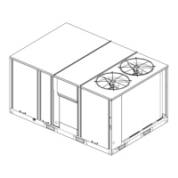
| Model | Voyager III |
|---|---|
| Refrigerant Type | R-410A |
| Compressor Type | Scroll |
| Dimensions | Varies by model |
| Weight | Varies by model |
| Heating Capacity | Varies by model |
| Power Supply | 3-phase |




 Loading...