PART-SVN121A-EN 13
Installation of TR200 VFD and Components
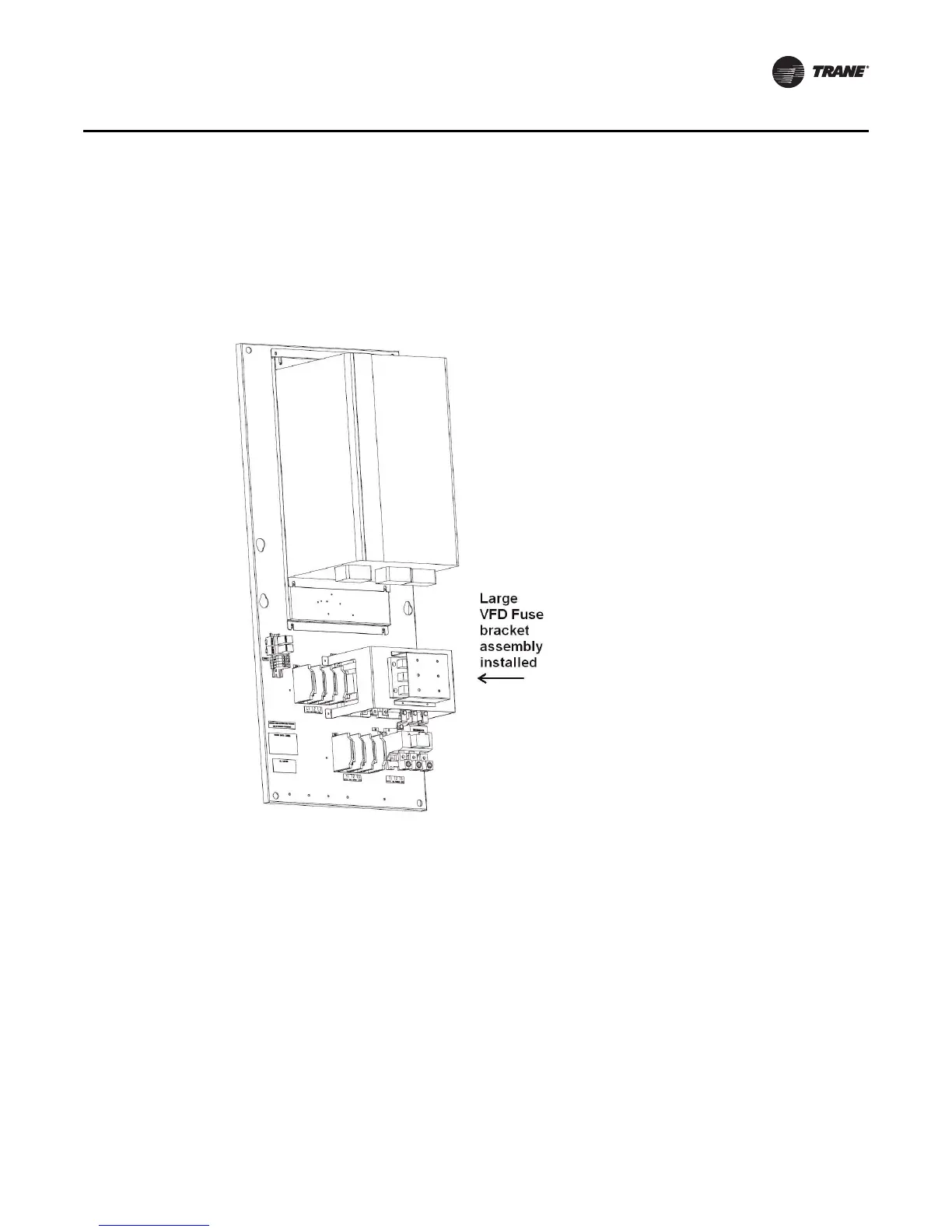
6 fuse studs to the fuse bracket so that each fuse will fit on two studs. Using the 4 screws, mount
this fuse bracket assembly directly to the existing TR1 panel similar to the figure below. Drilling
is required to mount the fuse bracket; use the fuse bracket as a drill template to mark the existing
panel (ensure a minimum of .5 inches through-air clearance between the bracket and all live
connections on the existing panel). Remove all metal shavings.
Note: The large VFD fuses are not actually installed onto the studs until after Power Supply Wiring
is connected. This is because the wire lug is the first item that stacks onto each fuse stud.
8. Ensure fuse guard mounting holes are accessible for installing the guard (after re-connecting
power wires).
Power Supply Wiring to TR200
The existing unit VFD schematic, along with the fuse modification drawing “TR200 Schematic,”
p. 14, may be used as a reference or specific wiring schematics can be found in “Wiring Diagram
Matrix,” p. 19.

 Loading...


