18-BC83D1-2 3
60’
Max
Vertical
Change
Standard
Line Set
60’ Max
Line Length
60’
Max
Vertical
Change
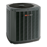
Unit Dimensions and Weight
Models H x D x W (in)
Weight* (lb)
4TWR3018C
29 x 30 x 33 161
4TWR3024C
29 x 30 x 33 163
4TWR3030B
33 x 30 x 33 193
4TWR3036B
33 x 34 x 37 227
4TWR3042B
33 x 34 x 37 219
4TWR3048B
37 x 34 x 37 234
4TWR3060B
41 x 34 x 37 248
* Weight values are estimated.
Section 2. Unit Location Considerations
2.1 Unit Dimensions and Weight
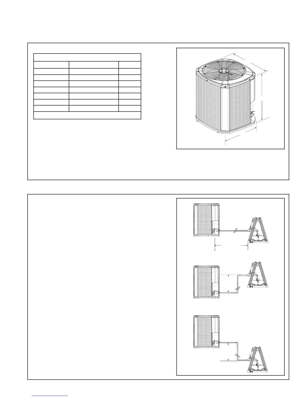
2.2 Refrigerant Piping Limits
1. The maximum length of refrigerant lines
from outdoor to indoor unit should NOT
exceed sixty (60) feet.
2. The maximum vertical change should not
exceed sixty (60) feet.
3. Service valve connection diameters are
shown in Table 5.1.
Note: For line lengths greater than sixty (60)
feet, Refer to Refrigerant Piping Application
Guide, SS-APG006-EN or Refrigerant Piping
Software Program, 32-3312-03 (or latest revi-
sion).
Table 2.1
When mounting the outdoor unit on a roof, be
sure the roof will support the unit’s weight.
Properly selected isolation is recommended to
alleviate sound or vibration transmission to the
building structure.
 Loading...