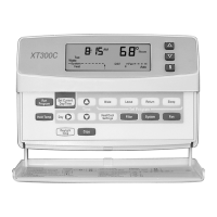
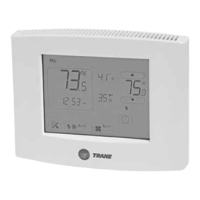
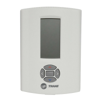
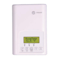
Trane XR203 Programmable Thermostat
Pub. No. 18HD50D1-1A-EN 12/2018 Part No. 37-7768003 3
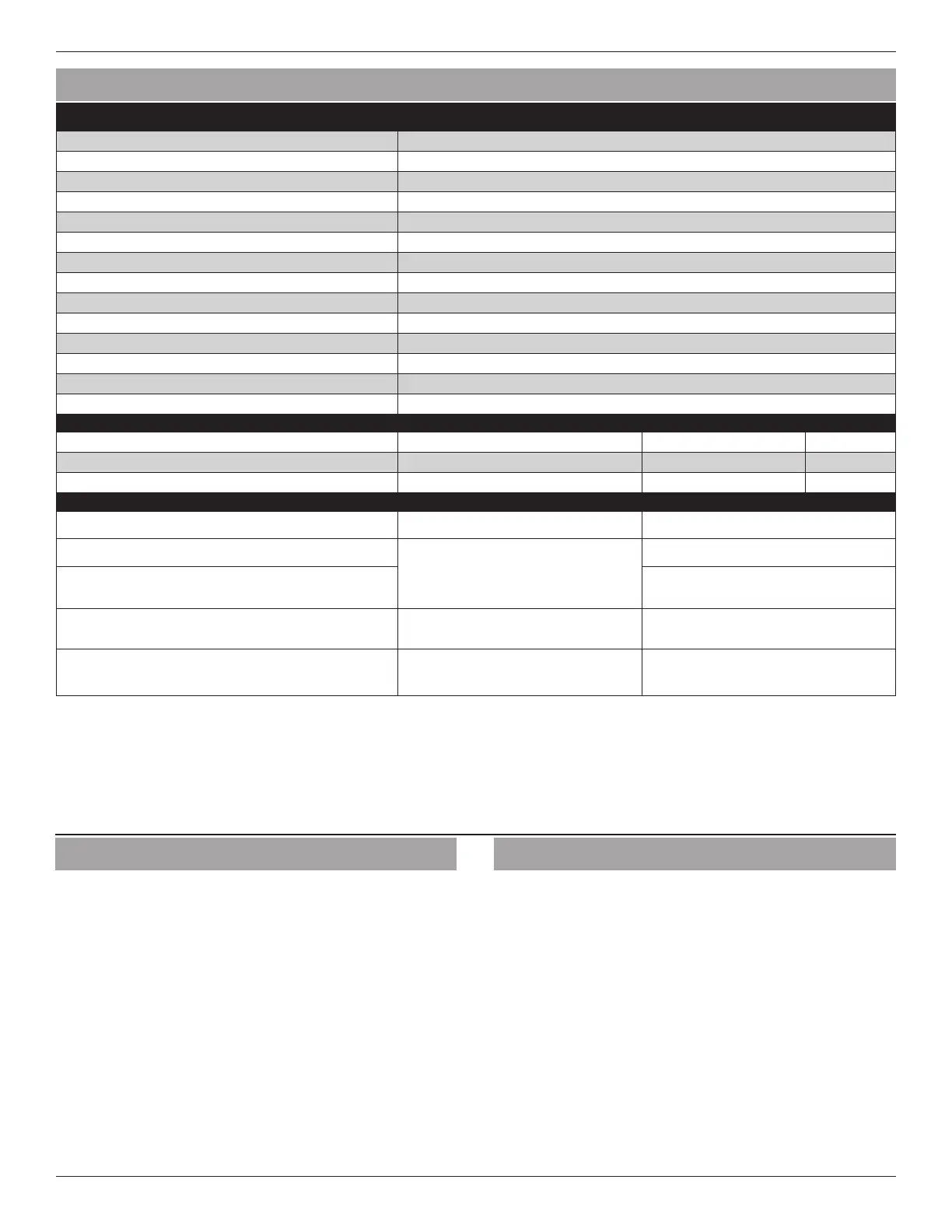
SPECIFICATION DESCRIPTION
Product Models TCONT203
Product XR 203
Size 3-3/4” x 6” x 1-1/8” (HxWxD)
Configurations Heat Pump, Heat/Cool, Dual Fuel, Dual Fuel Low Unrestricted Mode Only
Maximum Number of Stages 4 Stages Heat, 2 Stages Cooling
Operating Temperature 32°F to 105°F (0 to +41°C) / 90% RH Non Condensing
Shipping Temperature Range -20 to 150°F (-29 to +65°C)
Input Power (DC) Two 1.5V AA Alkaline
Input Power (AC) 20-30 VAC, NEC Class ll, 50/60 HZ
Terminal Load 1.5A per terminal, 2.5A maximum all terminals combined
Wire Usage 18 AWG
System Modes Auto, Heating, Cooling, Off, Emergency Heat
Fan Modes Auto, On, Program
Indoor Temperature Display Range 32°F to 99°F
RATED DIFFERENTIALS
Fast Medium Slow
Heat (Conventional Gas/Oil/Electric or HP Aux) 0.5°F 0.75°F 1.9°F
Central Air (Cool ) or HP (Heat/Cool) 0.9°F 1.2°F 1.7°F
THERMOSTAT APPLICATION GUIDE
Thermostat Configuration Options Thermostat Applications Maximum Stages Heat/Cool
Single Stage 1 No Heat Pump
Gas, Oil, Electric, Heat Only, Cool Only or
Heat/Cool Systems, 2 or 3 wire Hydronic
Zone (Hot Water or Steam) Systems, 24 Volt
or Millivolt
1+1
Multi Stage 2 No Heat Pump 2+2
Heat Pump 1
Single Stage Compressor Heat Pump
Single Stage Compressor Heat Pump
Systems - up to 2 Stages Aux./Emergency
Heat
3+1
Heat Pump 2
Two Stage or Two Compressor Heat Pump
Two Stage or Two Compressor Heat Pump
systems - up to 2 Stages Aux./Emergency
Heat
4+2
*On every application, 24VAC loads should be reviewed to be sure the indoor unit control power transformer is adequately sized.
NOTE:
Use 18-gauge color-coded thermostat cable for proper wiring. Shielded cable is not typically required.
Keep this wiring at least one foot away from large inductive loads such as Electronic Air Cleaners, motors, line starters, lighting ballasts and
large distribution panels. Failure to follow these wiring practices may introduce electrical interference (noise) which can cause erratic system
operation.
All unused thermostat wire to be grounded at indoor unit chassis ground only. Shielded cable may be required if the above wiring guidelines
cannot be met. Ground only one end of the shield to the system chassis.
2. Product Specifications
3. General Information
3.1 Overview
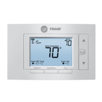
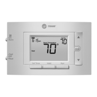
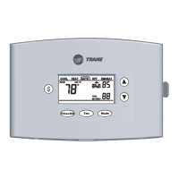
The 203 is a programmable push button thermostat with
a 3.5’’ backlit display. The 203 features a scheduling mode
that can operate a 7-day program, 5-1-1 program or operate
in a non-programmable mode.
3.2 Contents
— 1-Thermostat
— 1-Sub-base
— 2-Phillips slotted head mounting screws
— 2-Nylon Drywall Anchors
— 1-Installation Guide / User Guide
3.3 Accessories
Wall Cover Plate (BAYCOVR200A)
4. Installation
4.1 Location
The 203 is designed for installation in climate controlled living
spaces. Place the unit in a central location with good circulation.
For proper temperature sensing, avoid exposing the 203 to heat
radiated from lamps, sun light, fireplaces or any other radiant heat
source.
Avoid locations close to windows, behind doors or alcoves with
poor air circulation, adjoining outside walls, or doors that lead to
the outside.
Select a location that prevents the 203 from being directly exposed
to air currents from supply registers or ceiling fans.
Mount the Control on a section of interior wall that does not
contain hot or cold water pipes or duct work.