12 18-HD66D1-4
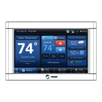
Static Pressure Sensor
Terminal
Name
Description Color Used:
Gnd/Grn Ground
Signal/Blk Output Signal (5VDC)
+5V/Red Power (5VDC)
Connect Static Pressure Transducer Wires
8
7
Connect the Green wire from the Static Pressure
transducer to the terminal labeled “Gnd/Grn.”
Connect the Black wire from the Static Pressure
transducer to the terminal labeled “Signal/Blk.”
Connect the Red wire from the Static Pressure
transducer to the terminal labeled “+5V/Red.”
Place the cover on the Pressure Transducer
Enclosure once the tubing is attached and wiring is
complete.
Zone Dampers
Sensors
Reserved
Reserved
Reserved
Static Press
Gnd/Grn
Signal/Blk
+5V/Red
TemperatureNon Comm Zone Sensor
Discharge Air
Discharge Air
Return Air
Return Air
Mixed Air
Mixed Air
Zone 1 or 5
Zone 1 or 5
Zone 2 or 6
Zone 2 or 6
Zone 3 or 7
Zone 3 or 7
Zone 4 or 8
Zone 4 or 8
Zone
1 or 5
ZONES
1 - 4
5 - 8
Indoor/
Relay Panel
Comm
Outdoor
Comm Zone Sensor/
2nd Zone Panel
24V
Trans.
Common
PO/Open
PC/Closed
Zone
2 or 6
Common
PO/Open
PC/Closed
Zone
3 or 7
Common
PO/Open
PC/Closed
Zone
4 or 8
Common
PO/Open
PC/Closed
Comm
R
BDB
B
R
BD D
Temperature Sensors
Terminal
Name
Description Color Used:
Discharge Air Discharge Air Sensor
Discharge Air Discharge Air Sensor
Return Air
Optional Return Air Sensor
Return Air
Optional Return Air Sensor
Mixed Air
Optional Mixed Air Sensor
Mixed Air
Optional Mixed Air Sensor
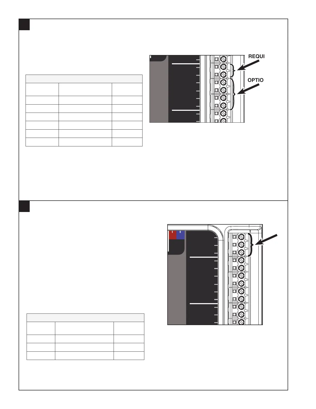
Connect Temperature Sensor Wires
Connect the required Discharge Air Temperature
Sensor wires to the terminals marked “Discharge
Air” as shown at right. Use a dedicated wire
bundle.
OPTIONAL: If using Return Air or Mixed Air temperature sensors, connect their wires to “Return Air” or
“Mixed Air” respectively.
NOTE: Wiring for the pressure sensor must be run in bundles separate from other 24 VAC circuits.
NOTE: Wiring for all temperature sensors must be run in bundles separate from other 24 VAC circuits.
Zone Dampers
Sensors
Reserved
Reserved
Reserved
Static Press
Gnd/Grn
Signal/Blk
+5V/Red
TemperatureNon Comm Zone Sensor
Discharge Air
Discharge Air
Return Air
Return Air
Mixed Air
Mixed Air
Zone 1 or 5
Zone 1 or 5
Zone 2 or 6
Zone 2 or 6
Zone 3 or 7
Zone 3 or 7
Zone 4 or 8
Zone 4 or 8
Zone
1 or 5
ZONES
1 - 4
5 - 8
Indoor/
Relay Panel
Comm
Outdoor
Comm Zone Sensor/
2nd Zone Panel
24V
Trans.
Common
PO/Open
PC/Closed
Zone
2 or 6
Common
PO/Open
PC/Closed
Zone
3 or 7
Common
PO/Open
PC/Closed
Zone
4 or 8
Common
PO/Open
PC/Closed
Comm
R
BDB
B
R
BD D
OPTIONAL
REQUIRED