13
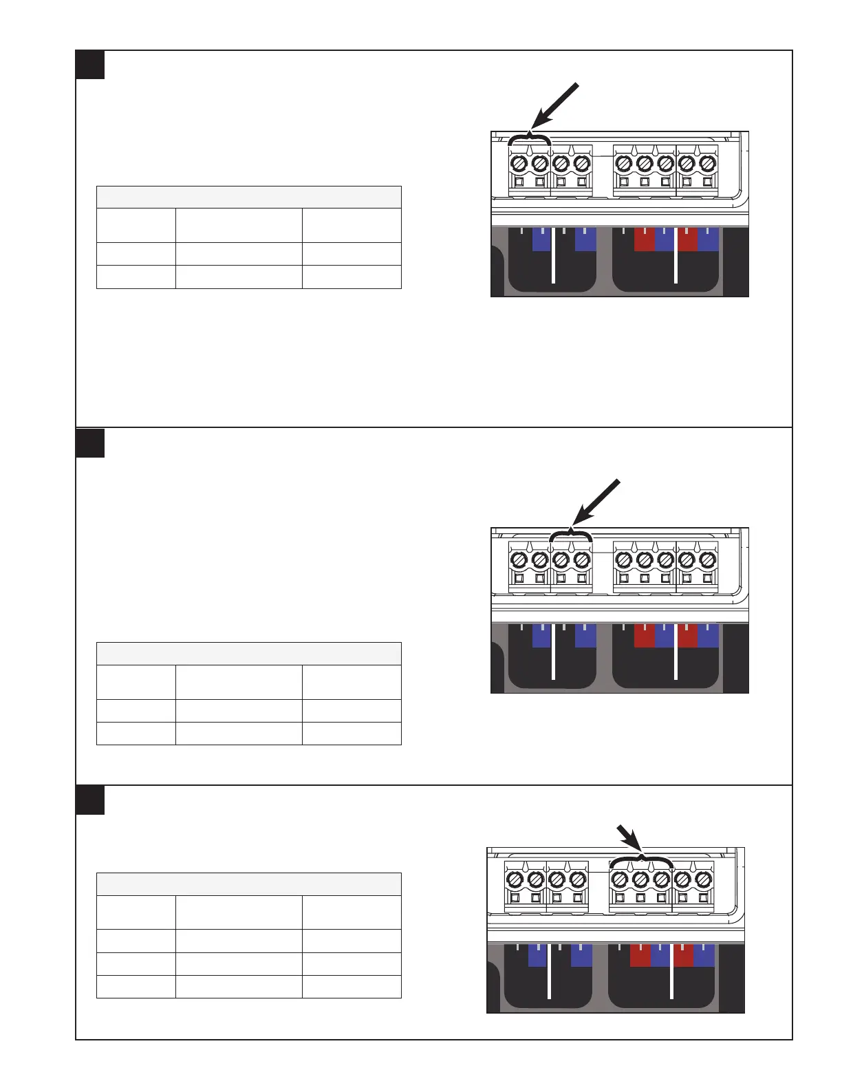
Connect Communicating Indoor Unit/Relay Panel
9
Connect the Indoor Unit or Relay Panel B and D
low voltage wiring to the Zone Panel’s “Indoor/
Relay Panel” B and D terminals.
NOTE: R from the Indoor Unit/Relay Panel is not
connected because power is provided from a field
supplied 24VAC transformer.
Indoor Unit or Relay Panel Connections
Terminal
Name
Description Color Used:
D Data
B Common
Zone Dampers
Sensors
Reserved
Reserved
Reserved
Static Press
Gnd/Grn
Signal/Blk
+5V/Red
TemperatureNon Comm Zone Sensor
Discharge Air
Discharge Air
Return Air
Return Air
Mixed Air
Mixed Air
Zone 1 or 5
Zone 1 or 5
Zone 2 or 6
Zone 2 or 6
Zone 3 or 7
Zone 3 or 7
Zone 4 or 8
Zone 4 or 8
Zone
1 or 5
ZONES
1 - 4
5 - 8
Indoor/
Relay Panel
Comm
Outdoor
Comm Zone Sensor/
2nd Zone Panel
24V
Trans.
Common
PO/Open
PC/Closed
Zone
2 or 6
Common
PO/Open
PC/Closed
Zone
3 or 7
Common
PO/Open
PC/Closed
Zone
4 or 8
Common
PO/Open
PC/Closed
Comm
R
BDB
B
R
BD D
Connect Wiring to Communicating Outdoor Unit
10
The Zone Panel provides an optional low voltage
connection point for a communicating outdoor unit.
The communicating outdoor requires B and D from
one location; this can either be from the indoor unit
or the Zone Panel.
NOTE: If a non-communicating outdoor unit is
installed, these connections will not be used.
Outdoor Unit Connections
Terminal
Name
Description Color Used:
D Data
B Common
Zone Dampers
Sensors
Reserved
Reserved
Reserved
Static Press
Gnd/Grn
Signal/Blk
+5V/Red
TemperatureNon Comm Zone Sensor
Discharge Air
Discharge Air
Return Air
Return Air
Mixed Air
Mixed Air
Zone 1 or 5
Zone 1 or 5
Zone 2 or 6
Zone 2 or 6
Zone 3 or 7
Zone 3 or 7
Zone 4 or 8
Zone 4 or 8
Zone
1 or 5
ZONES
1 - 4
5 - 8
Indoor/
Relay Panel
Comm
Outdoor
Comm Zone Sensor/
2nd Zone Panel
24V
Trans.
Common
PO/Open
PC/Closed
Zone
2 or 6
Common
PO/Open
PC/Closed
Zone
3 or 7
Common
PO/Open
PC/Closed
Zone
4 or 8
Common
PO/Open
PC/Closed
Comm
R
BDB
B
R
BD D
Connect Wiring to Communicating Zone Sensors and 2nd Zone Panel (if used)
11
Connect wiring (D, R, B) between each Communicating Zone
Sensor using the provided clamp-style wire connectors. If
required, a 2nd Zone Panel can also be connected.
See Communicating Zone Sensor Installer’s Guide for setup information
Power Supply Connections
Terminal
Name
Description Color Used:
D Data
R 24V Hot
B Common
Zone Dampers
Sensors
Reserved
Reserved
Reserved
Static Press
Gnd/Grn
Signal/Blk
+5V/Red
TemperatureNon Comm Zone Sensor
Discharge Air
Discharge Air
Return Air
Return Air
Mixed Air
Mixed Air
Zone 1 or 5
Zone 1 or 5
Zone 2 or 6
Zone 2 or 6
Zone 3 or 7
Zone 3 or 7
Zone 4 or 8
Zone 4 or 8
Zone
1 or 5
ZONES
1 - 4
5 - 8
Indoor/
Relay Panel
Comm
Outdoor
Comm Zone Sensor/
2nd Zone Panel
24V
Trans.
Common
PO/Open
PC/Closed
Zone
2 or 6
Common
PO/Open
PC/Closed
Zone
3 or 7
Common
PO/Open
PC/Closed
Zone
4 or 8
Common
PO/Open
PC/Closed
Comm
R
BDB
B
R
BD D