14 18-HD66D1-4
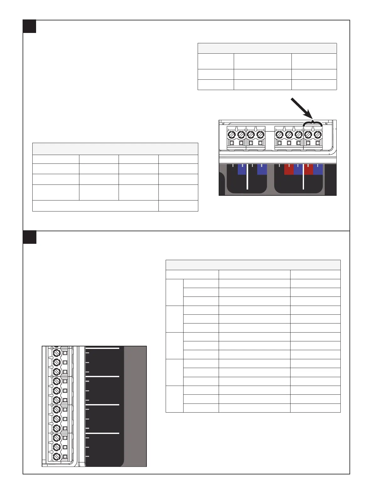
Mount the Zone Panel 24V Power Supply
12
A separate, field-supplied 24 volt transformer is required
to power the Zone Panel, communicating sensors
and dampers. VA sizing of the transformer will be
dependant on the total VA of all installed zone panels,
communicating sensors and zone dampers. Connect this
dedicated 24 volt source to the R and B terminals.
NOTE: To prevent possible communication errors,
connect the B/common of the field-supplied Zone Panel
transformer to the indoor unit B/common or equipment
ground.
EXAMPLE:
*Add the VA of each communicating sensor
Power Supply Connections
Terminal
Name
Description Color Used:
R 24V Hot
B Common
Transformer Sizing Example (8 Zone System, 1 Damper per Zone)
Component Qty VA (ea) Total VA
Zone Panel 2 2 4
Zone Dampers* 8 1.5 12
Communicating
Sensor
4 2 8
Minimum Transformer VA Required 24
Zone Dampers
Sensors
Reserved
Reserved
Reserved
Static Press
Gnd/Grn
Signal/Blk
+5V/Red
TemperatureNon Comm Zone Sensor
Discharge Air
Discharge Air
Return Air
Return Air
Mixed Air
Mixed Air
Zone 1 or 5
Zone 1 or 5
Zone 2 or 6
Zone 2 or 6
Zone 3 or 7
Zone 3 or 7
Zone 4 or 8
Zone 4 or 8
Zone
1 or 5
ZONES
1 - 4
5 - 8
Indoor/
Relay Panel
Comm
Outdoor
Comm Zone Sensor/
2nd Zone Panel
24V
Trans.
Common
PO/Open
PC/Closed
Zone
2 or 6
Common
PO/Open
PC/Closed
Zone
3 or 7
Common
PO/Open
PC/Closed
Zone
4 or 8
Common
PO/Open
PC/Closed
Comm
R
BDB
B
R
BD D
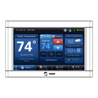
Connect the Dampers
13
The dampers will have the same terminal
designation as the Zone Panel.
For each damper:
• Connect Common from the damper to
Common on the Zone Panel.
• Connect PO/Open from the damper to
PO/Open on the Zone Panel.
• Connect PC/Close from the damper to
PC/Close on the Zone panel.
Repeat this for each damper installed (see
the damper installer’s guide).
Zone Dampers
Terminal Name Description Color Used:
Reserved Common
Reserved Power Open
Reserved Power Close
Zone 1
or 5*
Common Common
PO/Open Power Open
PC/Close Power Close
Zone 2
or 6*
Common Common
PO/Open Power Open
PC/Close Power Close
Zone 3
or 7*
Common Common
PO/Open Power Open
PC/Close Power Close
Zone 4
of 8*
Common Common
PO/Open Power Open
PC/Close Power Close
* Zones 5–8 are only when a second zone panel is used.
NOTES:
• 60 second drive dampers are the default. 15-60 second dampers
can be used, timing must be set at the 950/1050 Control.
• Up to 4 dampers may be used per zone (6 VA Max.).
• Mixing dampers from multiple manufacturers in the same zone is
not permitted.
Zone Dampers
Sensors
Reserved
Reserved
Reserved
Static Press
Gnd/Grn
Signal/Blk
+5V/Red
TemperatureNon Comm Zone Sensor
Discharge Air
Discharge Air
Return Air
Return Air
Mixed Air
Mixed Air
Zone 1 or 5
Zone 1 or 5
Zone 2 or 6
Zone 2 or 6
Zone 3 or 7
Zone 3 or 7
Zone 4 or 8
Zone 4 or 8
Zone
1 or 5
ZONES
1 - 4
5 - 8
Indoor/
Relay Panel
Comm
Outdoor
Comm Zone Sensor/
2nd Zone Panel
24V
Trans.
Common
PO/Open
PC/Closed
Zone
2 or 6
Common
PO/Open
PC/Closed
Zone
3 or 7
Common
PO/Open
PC/Closed
Zone
4 or 8
Common
PO/Open
PC/Closed
Comm
R
BDB
B
R
BD D