26 18-HD66D1-4
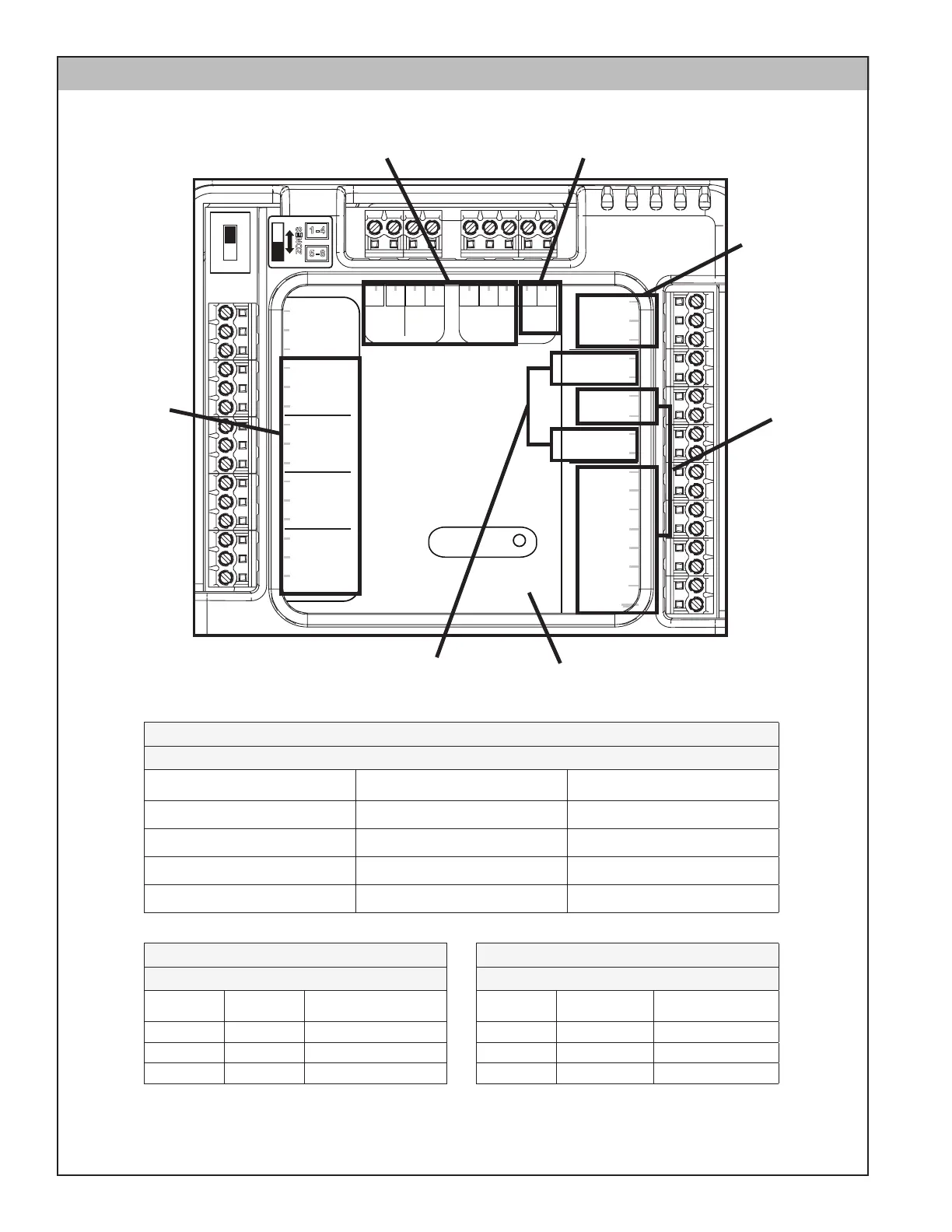
Section 8. Control Board Test Points
Zone Dampers
Sensors
Reserved
Reserved
Reserved
Static Press
Gnd/Grn
Signal/Blk
+5V/Red
TemperatureNon Comm Zone Sensor
Discharge Air
Discharge Air
Return Air
Return Air
Mixed Air
Mixed Air
Zone 1 or 5
Zone 1 or 5
Zone 2 or 6
Zone 2 or 6
Zone 3 or 7
Zone 3 or 7
Zone 4 or 8
Zone 4 or 8
Zone
1 or 5
ZONES
1 - 4
5 - 8
Indoor/
Relay Panel
Comm
Outdoor
Comm Zone Sensor/
2nd Zone Panel
24V
Trans.
Common
PO/Open
PC/Closed
Zone
2 or 6
Common
PO/Open
PC/Closed
Zone
3 or 7
Common
PO/Open
PC/Closed
Zone
4 or 8
Common
PO/Open
PC/Closed
Comm
R
BDB
B
R
BD D
SEE TABLE 5
SEE
TABLE 1
* See Note
SEE
TABLE 4
SEE
TABLE 6
SEE
TABLE 2
SEE
TABLE 3
TABLE 2
System Connections
Terminals Volts (DC)
Communication
Status
D & B 12 Good Communication
D & B 16 No Communication
D & B 0 Grounded or no power
TABLE 3
Power from Transformer
Terminals Volts (AC) Status
R & B 18 – 30 Good
R & B < 18 Low voltage
R & B 0 No voltage
TABLE 1
Zone Dampers
Terminals Volts (AC) Status
Common & PO/Open 24 Damper drive open
Common & PO/Open 0 Damper not being driven
Common & PC/Close 24 Damper drive closed
Common & PC/Close 0 Damper not being driven
* Status LED (non-functional) may be present on early production models.