- 34 -
17. EXCITATION OUTPUTS & POWER SUPPLY
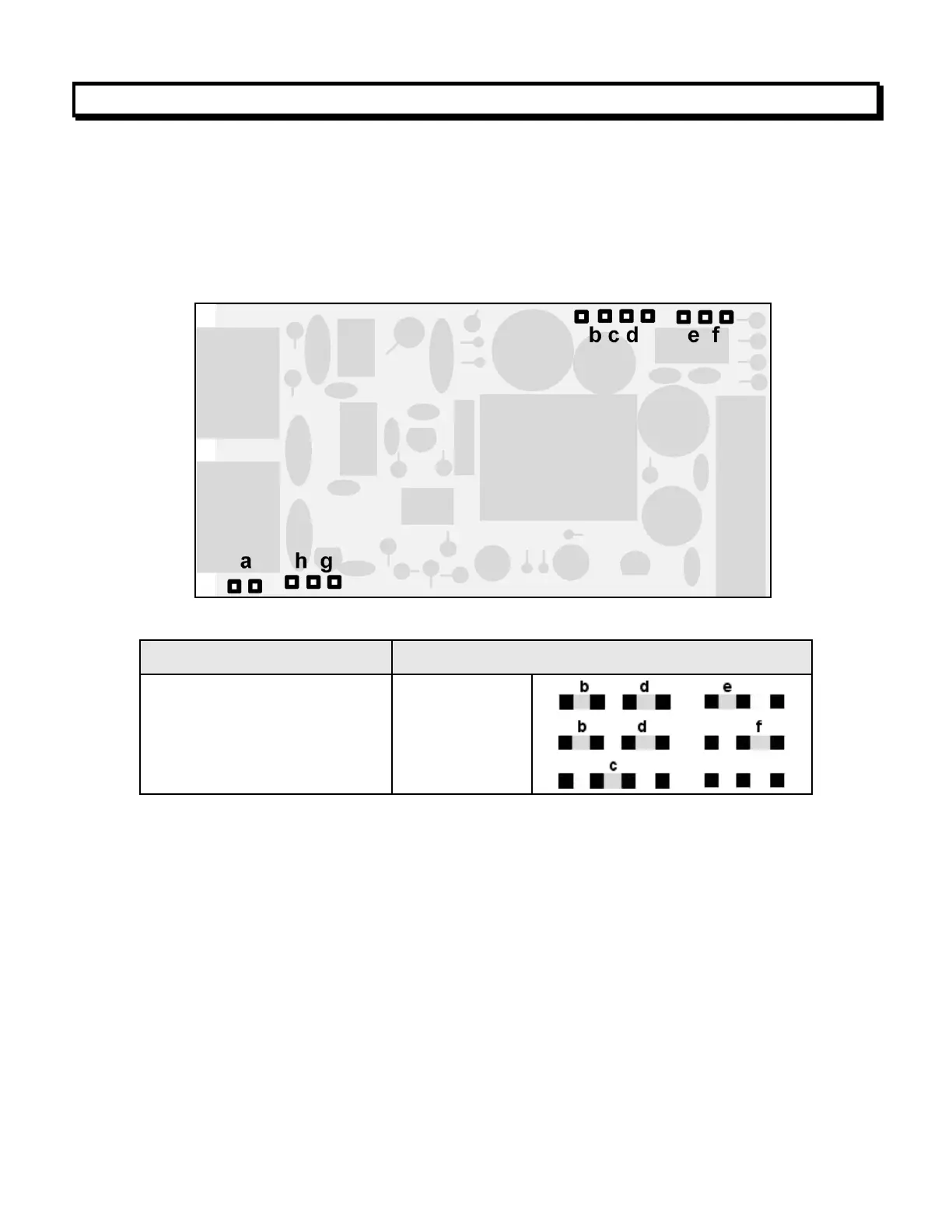
Three isolated transducer excitation output levels are available from the power supply board.
These are selectable via jumpers b, c, d, e, f in the upper right of the board, as illustrated.
In addition, the board provides three jumper positions for special features. The same jumper
locations apply to the universal power supply (85-264 Vac) and to the low voltage power
supply (12-32 Vac or 10-48 Vdc).
5 Vdc ±5%, 100 mA max
10 Vdc ±5%, 120 mA max
24 Vdc ±5%, 50 mA max
SELECTION OF OTHER JUMPERS
Jumper a - Front panel menu lockout, locked when installed. (See Section 8)
Jumper g - Provides +5V power output at P1-4 when installed.
Jumper h - Connects "Control Input 2" to P1-4 when installed.