- 23 -
13. LOAD CELL & MICROVOLT SIGNAL CONDITIONER
This section provides setup instructions to set up the DPM-3 signal conditioner for use with
load cells or strain gauges, or as a microvolt meter. The meter’s built-in, isolated 10 Volt,
120 mA excitation supply will power up to four 350 ohm load cells in parallel.
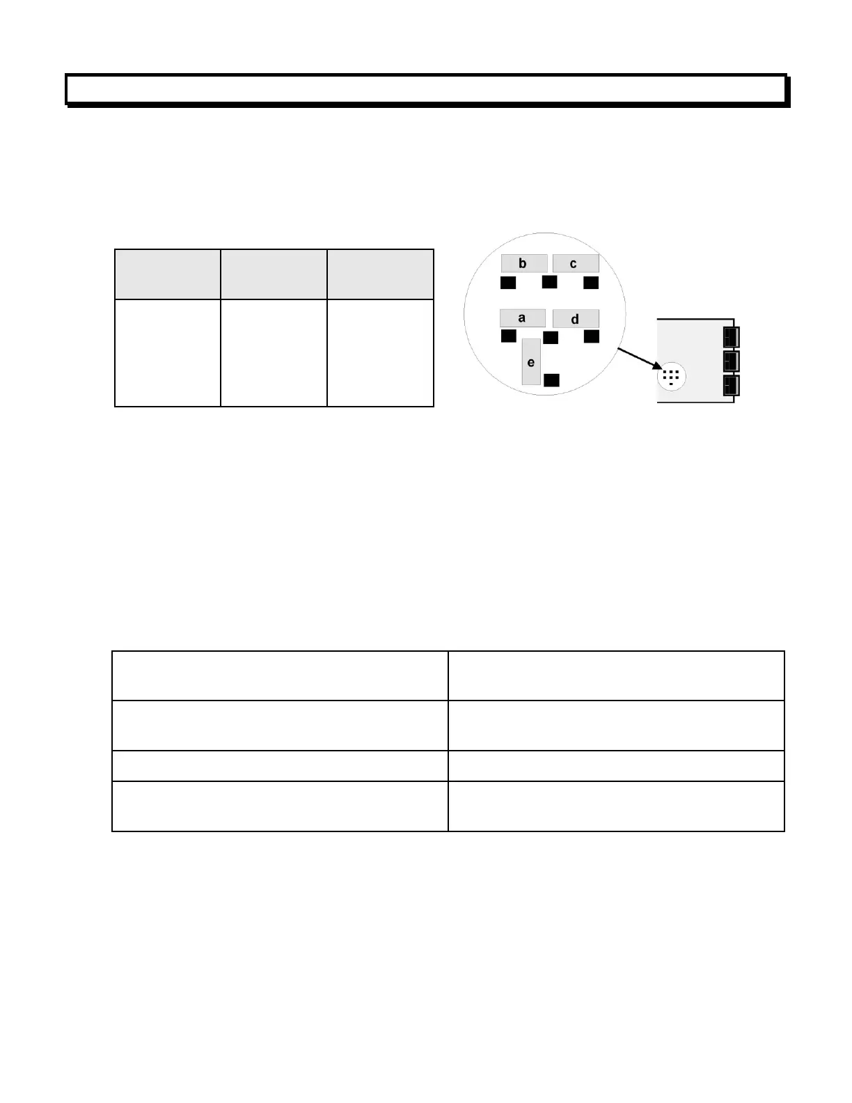
13.1 RANGE SELECTION VIA JUMPERS
Notes 1. See Section 17 to select 10V excitation.
2. Jumpers are 2.5 mm (0.1”).
3. If a TEDS sensor is connected, jumper for ± 50 mV.
13.2 MENU SELECTION
Display in engineering units can be programmed by either the Scale and Offset Method,
Coordinates of 2 Points Method, or Reading Coordinates of 2 Points Methods.
With the Scale and Offset Method, scale and offset are calculated as follows, and are
then entered manually. The example below is for 0 to 20 mV = 0 to 100.00.
Input span = Hi signal in – Lo signal in
Input ratio =Input range / Input span
Input span = 20 mV – 0 mV = 20 mV
Input ratio = 20 mV / 20 mV = 1.00
Display span = Hi display – Lo display
Display ratio = FS Display / Display span
Display span = 10000 – 0000 = 10000
Display ratio = 20000 / 10000 = 2.00
Scale Factor = Input ratio / Display ratio
Scale Factor = 1.00 / 2.00 = 0.5000
Offset = – (Lo signal in / Input span) x
Display span + Lo display
Offset = – (0 mV / 20 mV x 10000) + 0000
= 0000
With the Coordinates of 2 Points Method, values for low signal input, low display
reading, high signal input and high display reading must be entered manually. For
example, if the desired scaling is 0 to 30 mV = 0 to 500.0, the 50 mV full scale range
would be selected and values would be entered as follows:
Lo in = 00.000 Lo rd = 0000.0
Hi in = 30.000 Hi rd = 0500.0
In the Coordinates of 2 Points example below, 0 to 20 mV = 00000 to 50000. During
setup, it may be necessary to enable some menu items. See Section 8 for information.
± 20 mV
± 50 mV
± 100 mV
± 250 mV
± 500 mV
± 20000
± 50000
± 10000
± 25000
± 50000