- 8 -
6. MECHANICAL ASSEMBLY
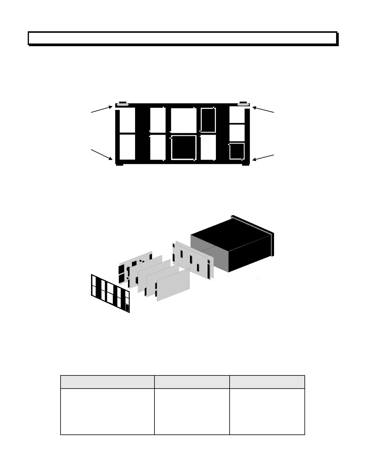
REMOVING THE REAR PANEL
First remove any connectors. Use one hand to press in the two sides of the rear of the
case, and the other hand to press down the two protruding tab releases at the top of the
rear panel (see figure below). This will unhook the rear panel from the case.
REMOVING THE ELECTRONICS
With the rear panel removed, grasp the power supply board to the left and signal condi-
tioner board to the right, and carefully slide the electronic assembly out through the rear of
the case (see figure below).
INSTALLING NEW OPTION BOARDS
Options boards plug into the main board at the front of the meter. These are plug-and-play
and may installed in the field. They will be recognized by the software, which will provide
access to the menu items associated with that board. If necessary, remove rear panel
knockouts for new boards. Boards plug into connectors as follows:
Power supply
Relay board
Serial interface board
Analog output board
Signal conditioner board
Retaining tab
with tab release
Retaining tab
with tab release