EasyManuals Logo

Transducer Techniques DPM-3 User Manual

Transducer Techniques DPM-3
53 pages
To Next Page IconTo Next Page
To Previous Page IconTo Previous Page
Page #6 background imageLoading...
Page #6 background image
- 6 -
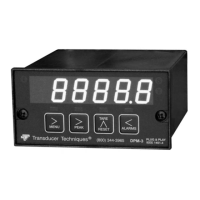
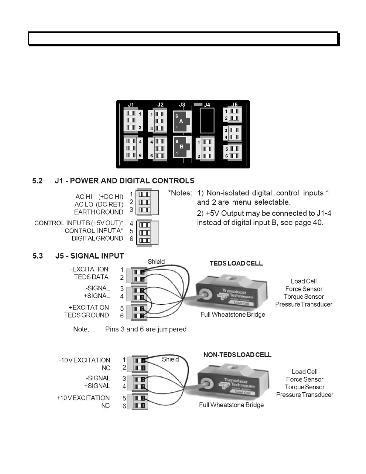
5. CONNECTOR WIRING INFORMATION
5.1 CONNECTOR LOCATION
Connectors for signal and power are UL-rated screw-clamp terminal blocks that plug into
mating jacks on the printed circuit board. Communication connectors can be a USB jack, a
single RJ11 jack for RS232, dual RJ11 jacks for RS485, or dual RJ45 jacks for RS485.
Note: For wiring color, refer to Load Cell Calibration Certificate or to
www.transducertechniques.com/wiring-color-code.aspx

Questions and Answers:

Question and Answer IconNeed help?

Do you have a question about the Transducer Techniques DPM-3 and is the answer not in the manual?

Transducer Techniques DPM-3 Specifications

General IconGeneral
BrandTransducer Techniques
ModelDPM-3
CategoryMeasuring Instruments
LanguageEnglish

Related product manuals