- 9 -
Note: Corresponding main board and option board connectors have the same number of
electrical lines. When an option board is correctly installed, the top and bottom edges of
the main board and option board are aligned.
REASSEMBLING YOUR METER
Slide the electronics assembly into the case until the display board is seated flush against
the front overlay. Insert the bottom tabs of the rear panel into the case, then carefully align
the board connectors with the openings in the rear panel. If necessary, remove any rear
panel knockouts for new option boards that may have been installed. Ensure that all option
boards are properly aligned with the molded board retaining pins on the inside of the rear
panel. With the rear panel in place, reinstall the input/output screw clamp terminal plugs.
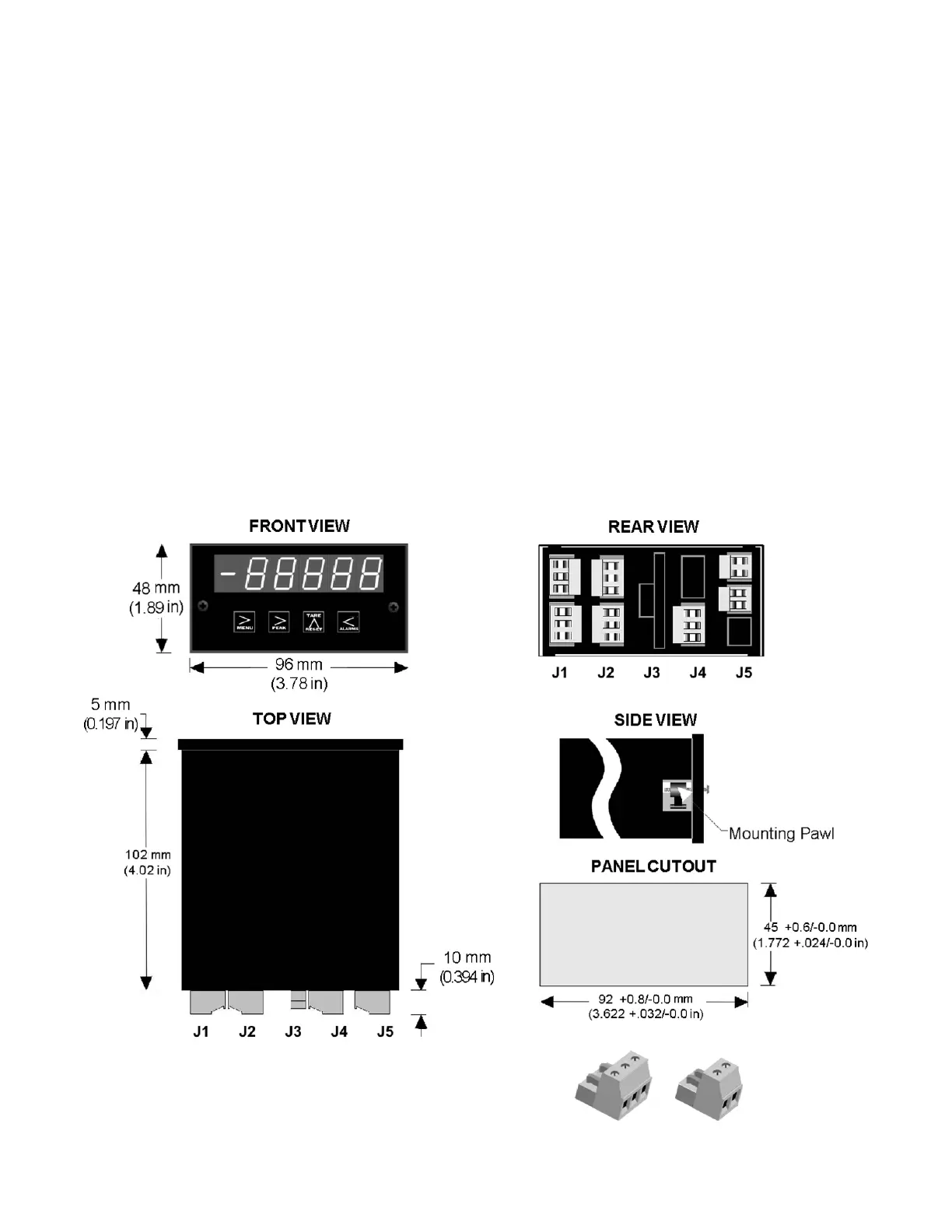
PANEL MOUNTING
Ensure that the panel mounted gasket is in place against the back of the bezel. Turn the
two mounting screws counterclockwise until the space between the mounting pawl and the
rear of the gasket is greater than the panel thickness. Insert the meter in the panel cutout.
Turn the mounting screws clockwise until the meter is securely mounted in the panel. Do
not overtighten.
The DPM-3 uses UL / VDE rated detachable
screw terminal connectors for signal and power.