Using Status LEDs
Ethernet Ports
JACE-6 Mounting and Wiring Instructions
Part Number 10821 Published: April 19, 2007
17
Using Status LEDs
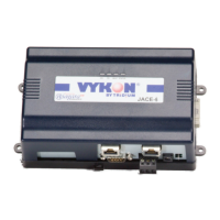
The JACE-6 controller includes several LEDs that can help determine the status of the unit. They are located in
two places: the top of the controller (visible through the cover), and for serial ports, on the bottom board (only
with cover removed). From left-to-right these LEDs include:
• Ethernet Ports
• Heartbeat
• Status
• Serial Ports
Refer to Figure 2 on page 6 for the exact locations of status LEDs on the JACE-6 controller.
Ethernet Ports
Each Ethernet port (“LAN2”, “LAN1”) has one green LED, visible on the top cover.
A “LANx” LED indicates activity on that port as follows:
• Off—No Ethernet link is made
• On—Ethernet link is present, but no activity on the LAN
• Blinking—Ethernet link is present with data activity on the LAN.
Heartbeat
The “BEAT” LED is located to the right of the Ethernet status LEDs, and is yellow. Under normal operation,
this LED should blink about once per second. If the heartbeat LED stays on constantly, does not light, or blinks
very fast (more than once per second), contact System Engineering for technical support.
Caution During boot-up, the heartbeat LED blinks in a 90% on — 10% off pattern. Do not remove power
during this time, or data loss may result (I/O module’s firmware upgrade may be in progress).
Status
The “STATUS” LED is located to the right of the heartbeat (“BEAT”) LED, and is green. This LED provides a
CPU machine status check, and should remain lit whenever the JACE-6 is powered. If the STATUS LED does
not light while power is applied, contact System Engineering for technical support.
Serial Ports
LEDs for the two serial ports are located on the JACE-6’s bottom board, on the opposite side of the RS-232 and
RS-485 ports (see Figure 2 on page 6). Labels “COM1” and “COM2” correspond to the software configuration
of the COM ports. LEDs show the transmit and receive activity for the serial ports and optional modem.
Note You must remove the cover to the serial port LEDs. See “Removing and Replacing the Cover,” page 6.
• The yellow transmit LED indicates that the JACE-6 is sending data out the serial port over a
communications line to a connected device.
• The green receive LED indicates that the JACE-6 is receiving data from a connected device.
These LEDs provide a fixed on-time when data is detected on the port. If the receive LED is on constantly, this
indicates a problem with the communications channel, such as a shorted wire or reversed wiring.

 Loading...