Wiring Details
Grounding
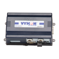
JACE-6 Mounting and Wiring Instructions
Part Number 10821 Published: April 19, 2007
9
Wiring Details
See Figure 2 on page 6 to locate connectors and other components on the JACE-6 controller.
Make connections to the JACE in the following order.
1. Install any option boards (LON, RS-485, RS-232, or modem) in option slots 1 and 2. See “Mounting
Option Cards,” page 7 for a general procedure. For complete details, refer to the specific mounting and
wiring guide that shipped with the option board.
2. Connect supplied earth grounding wires (with spade connector) from the earth ground lug on the JACE-6
and any accessory modules (if used) to a nearby earth grounding point. See “Grounding” for details.
3. Prepare power wiring (leave the unit powered off). See “Power Wiring” for details.
4. Connect communications cables. See “Communications Wiring,” page 12 for ports available on the
JACE-6 base unit. For ports on any installed option board (LON, RS-485, modem) see the specific
mounting and wiring guide for any additional details.
5. If IO accessory modules are installed, connect the I/O wiring. Refer to the appropriate mounting and
wiring guide for complete details.
6. Connect the backup battery to the JACE-6 battery connector, and apply power to the unit. See “Power Up
and Initial Checkout,” page 15.
Grounding
An earth ground spade lug (0.187") is provided on the base of the JACE-6 for connection to earth ground. For
maximum protection from electrostatic discharge or other forms of EMI, connect the supplied earth grounding
wire to this lug and a nearby earth ground (see Figure 3 on page 11). Keep this wire as short as possible.
Power is provided for JACE-6 plug-in accessory modules through the 20-pin accessory connectors. However,
you should also connect the earth ground spade lug of each accessory module to ground in the same manner.
IO-16 DIN-mountable, 16 points I/O module,
used to provide I/O points as noted.
Provides the following I/O points:
• 8 - Universal Inputs (UIs).
• 4 - Digital Outputs (DOs), SPST-relay type.
• 4 - Analog Outputs, 0–10Vdc type.
Up to four (maximum) IO-16 accessory modules are supported.
Wiring is covered in a separate document, see the
IO-16 Installation and Configuration Instructions.
IO-34
(available only
in some
markets)
DIN-mountable, combined 34 points I/O
with 24V isolated power module, used to
provide I/O points as well as power
JACE-6 from a dedicated, external,
Class-2, 24Vac transformer or a 24Vdc
power supply.
Only one IO-34 per JACE-6. Provides the following I/O points:
• 16 - Universal Inputs (UIs).
• 10 - Digital Outputs (DOs), SPST-relay type.
• 8 - Analog Outputs, 0–10Vdc type.
Up to 2 additional IO-16 modules can be used. Do not power the
IO-34 if using WPM-XXX.
Wiring is covered in a separate document, see the
IO-34 Installation and Configuration Instructions.
Table 2 JACE-6 accessory modules. (continued)
Model Description Notes
 Loading...