JACE-6 Mounting and Wiring Instructions
Published: April 19, 2007 Part Number 10821
Board Layout
Removing and Replacing the Cover
6
Removing and Replacing the Cover
You must remove the JACE-6 cover to connect the battery (new unit) or to replace the battery, and to install any
option boards. The cover snaps onto the base with four plastic tabs (two on each end).
To remove the cover, press in the four tabs on both ends of the unit, and lift the cover off.
Note If accessory modules are plugged into the JACE-6, you may need to slide them away from the unit to
get to the cover tabs.
To replace the cover, orient it so the cutout area for comm ports is correct, then push inwards to snap in place.
Board Layout
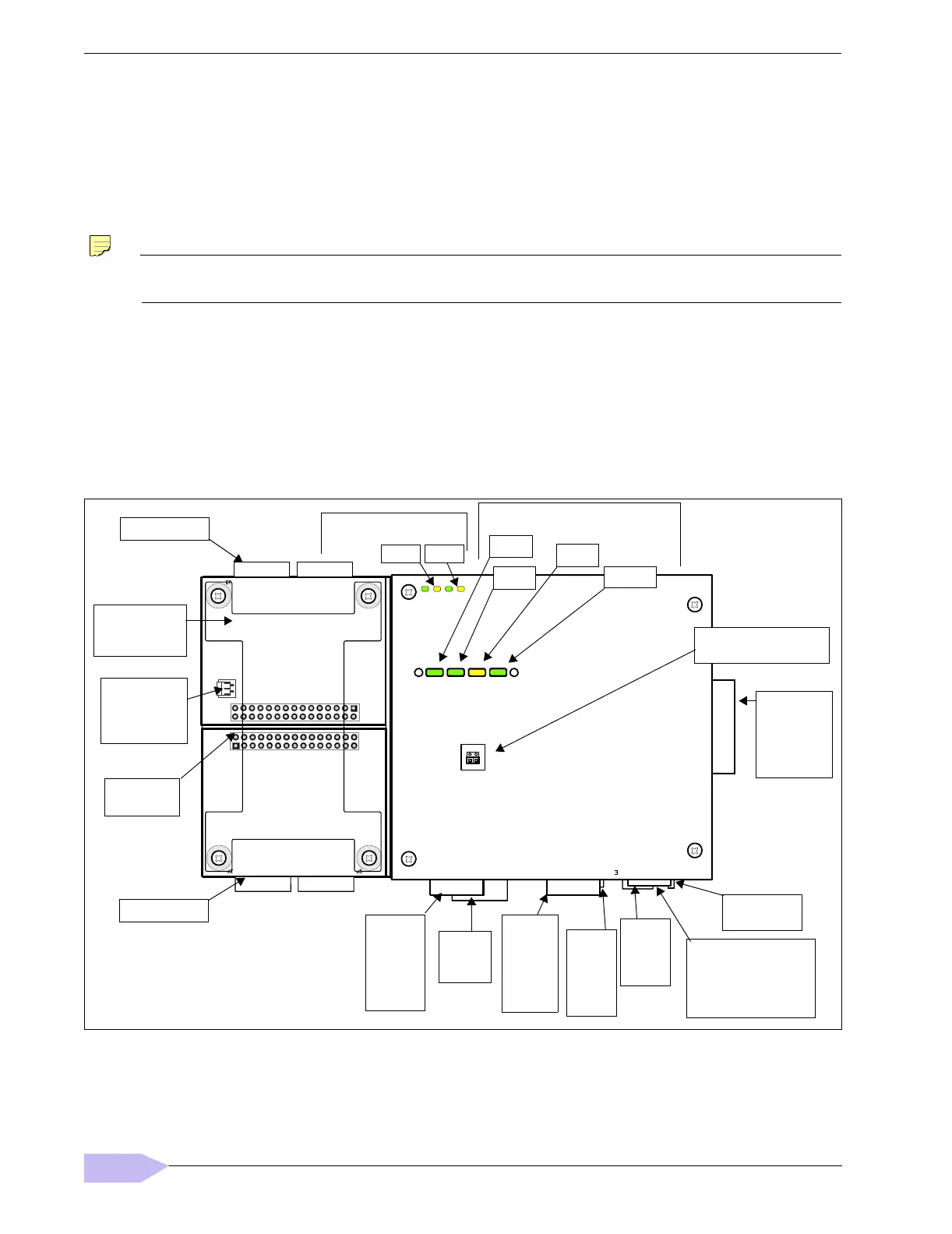
Figure 2 shows the location of LEDs, option slots, and other features of the JACE-6 with cover removed. For a
side view of communications ports and other features, see Figure 5 on page 13.
Figure 2 JACE-6 board layout details.
BATTERY
Option Slot 2
Option Slot 1
Battery Bracket
(on top of option
cards, if any)
Option Slot
Connectors
Status LEDs (visible with cover on):
LAN2
LAN1
BEAT
STATUS
20 Pin
Connector
(I/O and
Power
Modules)
Secondary
Ethernet
(RJ-45)
LAN2
(top
board)
RS-232
(DB-9)
COM1
Primary
Ethernet
(RJ-45)
LAN1
(top
board)
Barrel power
connector for wall
mounted power
module (WPM-XXX).
Earth Ground
Spade Lug
COM 1
COM 2
Serial port LEDs on bottom
board, remove cover to see:
Mode Jumper
(for serial shell access)
JACE Battery
Connector
(see Figure 6
on page 15)
USB
port
(top
board)
RS-485
(3-pos.)
COM2
(bottom
board)
 Loading...