JACE-6 Mounting and Wiring Instructions
Published: April 19, 2007 Part Number 10821
Wiring Details
Communications Wiring
14
Note If a modem option card (NPB-MDM) is installed, this port becomes disabled—except if rebooted with
the mode jumper (see Figure 2 on page 6) in the “Serial Shell” position.
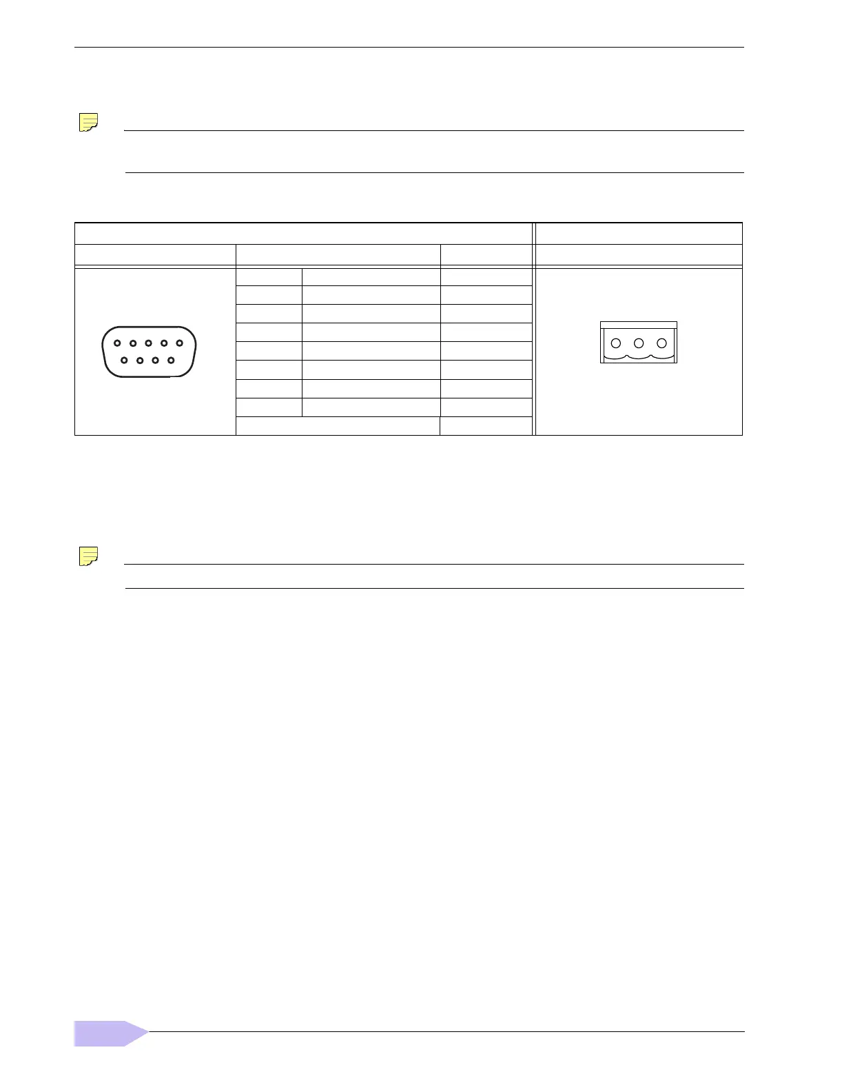
RS-485—An RS-485, optically isolated port uses a 3-position, screw terminal connector and always operates
as COM2. Wire to this connector with shielded 18-22AWG wiring (refer to the TIA/EIA-485 standard). As
shown in Table 3, the screw terminals (from left-to-right) are shield, plus (+), and minus (–).
USB —A single USB port is on the top board.
Note The USB port is for future use.
Table 3 Serial port (RS-232 and RS-485) pinouts.
Base RS-232 DB-9 Port (COM1) Base RS-485 Port (COM2)
Pinout References Signal DB-9 Plug Pin Pinouts
DCD Data carrier detect 1
RXD Receive data 2
TXD Transmit data 3
DTR Data terminal ready 4
GND Ground 5
DSR Data set ready 6
RTS Request to send 7
CTS Clear to send 8
not used on the JACE-6 9
DB-9 Plug (male)
1
5
6
9
3-position connector (male)
S
+
–
 Loading...