Wiring Details
Communications Wiring
JACE-6 Mounting and Wiring Instructions
Part Number 10821 Published: April 19, 2007
13
Note Prior to connecting cables, provide strain relief for them to prevent damage to the controller.
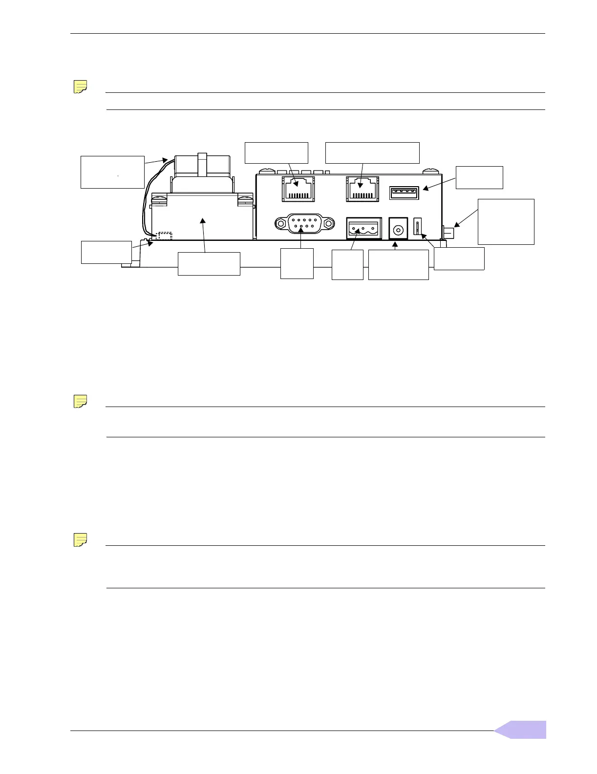
Figure 5 JACE-6 bottom side (cover removed).
Ethernet
Two, female 10/100-Mbit Ethernet connections are provided on the JACE-6. These are RJ-45 connectors
labeled LAN2 and LAN1. Use a standard Ethernet patch cable for connecting to a hub or Ethernet switch. An
activity LED for each Ethernet port is visible, and are labeled “LAN2” and “LAN1” on the cover.
The factory-default IP address for LAN1 on a JACE-6 is
192.168.1.12n, where the last numeral n in the
address matches the JACE-6’s serial number, and subnet mask is
255.255.255.0. By default, LAN2 on a
JACE-6 is disabled. Refer to the JACE NiagaraAX Install and Startup Guide for details on changing IP address.
Note Typically, you only use LAN1 (primary port), unless you have a specific application for isolating a
driver’s network traffic to a separate LAN, using LAN2. Do not use LAN2 as the primary port.
Serial
There are two serial ports on the JACE-6 base board. Each has a UART capable of operation up to 115,200 baud.
At the bottom of the board (see Figure 5), the left port is an RS-232 port using an DB-9 plug (male) connector.
To the right of this is a two-wire with shield, isolated RS-485 port, using a screw-terminal connector plug. In
addition, on the top board (to the right) is a third, standard USB port.
Note A green “receive” LED and yellow “transmit” LED are provided for each serial port. These LEDs are
located on the bottom board, on the opposite side of the serial connectors (see Figure 2 on page 6).
These LEDs are labeled on the board (COM1, COM2) and are not visible with the cover on.
RS-232—An RS-232 serial port using a male DB-9 connector always operates as COM1. You can use standard
DB-9 serial cables with this port. The JACE-6 is a serial DTE device, such another DTE device (PC, for
example) requires a “null modem” cable. If connecting the JACE-6 to a DCE device (modem, for example), a
straight-through cable is used. Table 3 provides standard serial DB-9 pinouts.
Battery in bracket
(on top of option
cards, if any)
JACE Battery
Connector
20 Pin
Connector
(I/O and Power
Modules)
Ethernet (RJ-45)
LAN 2
RS-232
(DB-9)
COM1
Primary Ethernet (RJ-45)
LAN 1
RS-485
(3-pos.)
COM2
Earth Ground
Spade Lug
Barrel power
connector for
WPM-XXX.
Option Slot area
(Slot #1 this side)
s+–
USB port
(future use)
 Loading...