NEWTON+ – Operational Manual
TRINITY
[4]
Introduction
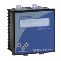
The relay is meant for flush mounting in a panel for connection to the electrical
system. The relay is the `intelligence' which controls the automatic system for
correction of the power factor. It senses the power factor by taking the ratio of the
true-rms KW of the system, and the KVA, for any one phase of the three phase
electrical system, when it operates in PF sensing mode. This means that phase and
neutral wire are connected as voltage inputs and the current of the same phase as
current input, for PF sensing mode of operation. For VAR sensing mode of
operation, the relay calculates the KVAR requirement of the system (VxIxsin). For
correct operation of the relay, however, there are some minimum system
requirements to be met. Unless the various points in the system which are
mentioned below are correctly setup, proper operation of the relay cannot be
expected.
System Considerations
1. If there is an imbalance loads in the three phases, the current transformer (CT)
must be mounted on the phase which has maximum load. All the load currents
and the capacitor current must pass through the bus on which the main CT is
mounted. Ensure that this condition is achieved for proper operation of relay.
2. The actual load current at the time of operation should be more then 5% of the
CT primary current rating. If this is not true, the relay will not operate.
3. The relay assumes a uniform loading of the three phase system. In case a
capacitor banks are not operating and the relay indicates LEAD power factor,
then the Main CT, S1 and S2 must be interchanged so as to correct the polarity
error.
4. The relay senses the power factor and switches ON or OFF the capacitor banks
(through contactors in a panel), to bring power factor closest to the set value.
For this the voltage must be within plus/minus 20 % of the rated voltage of the
relay. The voltage is to be sensed between any phase and neutral.
5. If need is failed for an external auto control, there is no harm in having one
provided, it must be implemented properly. An improperly implemented scheme
might cause the multi-operation of the panel. Make sure this is not the case
before putting the blame on the relay.
6. Capacitor CT rating must be calculated for autosense as,
CT Primary
Total KVAR X 1.6
7. Check all these points carefully in the system. If found ok, installation and
commissioning of the relay is easy.