8
F
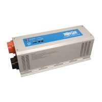
Remote Control Port: All models feature a 6-conductor
telephone-style jack on the front panel for use with an optional
remote control module (Tripp Lite model PINVSWRM, included
with all models). The remote module allows the Inverter to be
mounted out of sight in a compartment or cabinet, while operated
conveniently from your vehicle’s dashboard. See Mounting and
Operation sections instructions for use of the remote control
module.
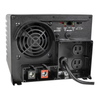
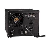
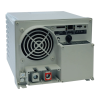
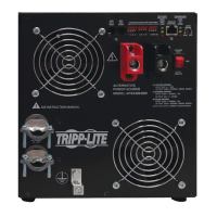
G
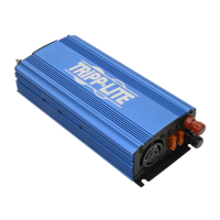
Cooling Fans: These fans regulate the internal temperature of
the inverter and prolong service life. They will only activate if the
temperature or load demand goes beyond the set thresholds.
H
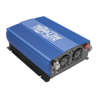
DC Input Terminals: These positive and negative terminals
connect to the battery via the included or user-supplied cabling.
See Battery Connection for instructions.
I
Main Ground Lug: Connects to an earth ground or a vehicle
grounding system in order to properly ground the inverter. See
Battery Connection for instructions.
J
LCD Display (Top of Unit): The LCD will display battery capacity
level, input/output voltage, output frequency, output current,
output load capacity (Watts) and fault codes.
Feature Identification
 Loading...