Home
Triton Electronics
Data Loggers
AMV3500
Page 39
Triton Electronics AMV3500 - Page 39
52 pages
Manual
Save Page as PDF
To Next Page
To Next Page
To Previous Page
To Previous Page
Loading...
© Triton Electr
onics Ltd 2022
Doc. AMV35003_
1.doc v1.04
PAGE
39
OF
52
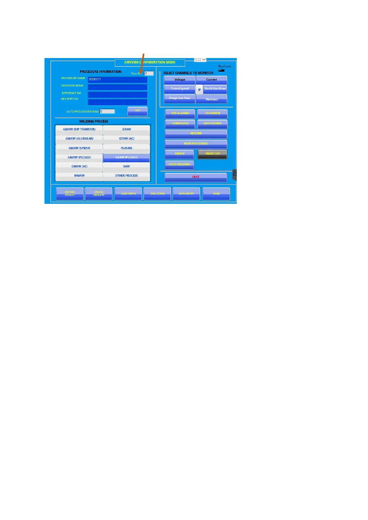
The configure scr
eens shows the
CAN number:
To change this CAN’s
details, press
EDI
T.
To start a new se
t of cans, press NEW
PROCEDURE
When ready press
DONE to start
welding.
38
40
Table of Contents
Main Page
Table of Contents
2
Starting and Connecting the AMV3500
4
Connecting the Sensors
4
Current Sensor
4
Voltage Connections
5
Wire Feed Sensor
5
Temperature Sensor
5
Gas Flow Sensor
6
Travel Speed Sensor
6
Voltage Breakout Box (P316)
6
4-20Ma Breakout Box (P362)
6
Charging the AMV3500
7
Starting the AMV3500
7
Main Operating Screens and Menus
7
AMV3500 Configuration Menu
7
Set Alarms
8
Calibrate
8
Configure
9
Main
9
Heat Input
10
Trigger
11
Maintenance
12
Additional
12
Resume
13
New Procedure
13
About
14
Stud Welding
15
Load Configuration
15
Save Configuration
15
Data Export
16
Monitor Screen
17
Oscilloscope Mode
18
Printer Options
19
Pass Complete
21
Arc Values
21
Enter Pass Length
22
Pass Summary Values
22
Graph
23
Procedure
23
Summary PDF
23
Procedure Complete
25
Printer Controls
26
Configure Screen
26
Monitor Screen
27
To Print an Average at a Specific Second Interval
28
Saving the Values
29
Suggested Setting
29
AMV Final File Uploader
30
How to Guides
32
Monitor a GTAW, GMAW or MMAW Procedure
32
Setup to Monitor an AC SAW Procedure
40
Use F1 and F2 Function Buttons
48
Start a New Procedure
48
Record Welding - F1
49
Record Welding F2
50
Summary
52