Installation
8
cylinder on the opposite side of the cistern to
the float operated valve (see fig.2). This
minimises air ingress into the pipework.
Plumbing options other than those outlined in
these fitting instructions could impair the
performance. For example, if hot and cold
connections are made after draw-off points to
other outlets, (eg. washing machine, taps, etc.)
it could result in unstable flows and
temperatures should other appliances operate at
the same time.
Run the hot and cold pipework to the shower
position, making sure that the pipework does
not rise above the level of water in the cold
cistern at any point to avoid air locks. Under
normal site conditions 15mm pipework will be
adequate.
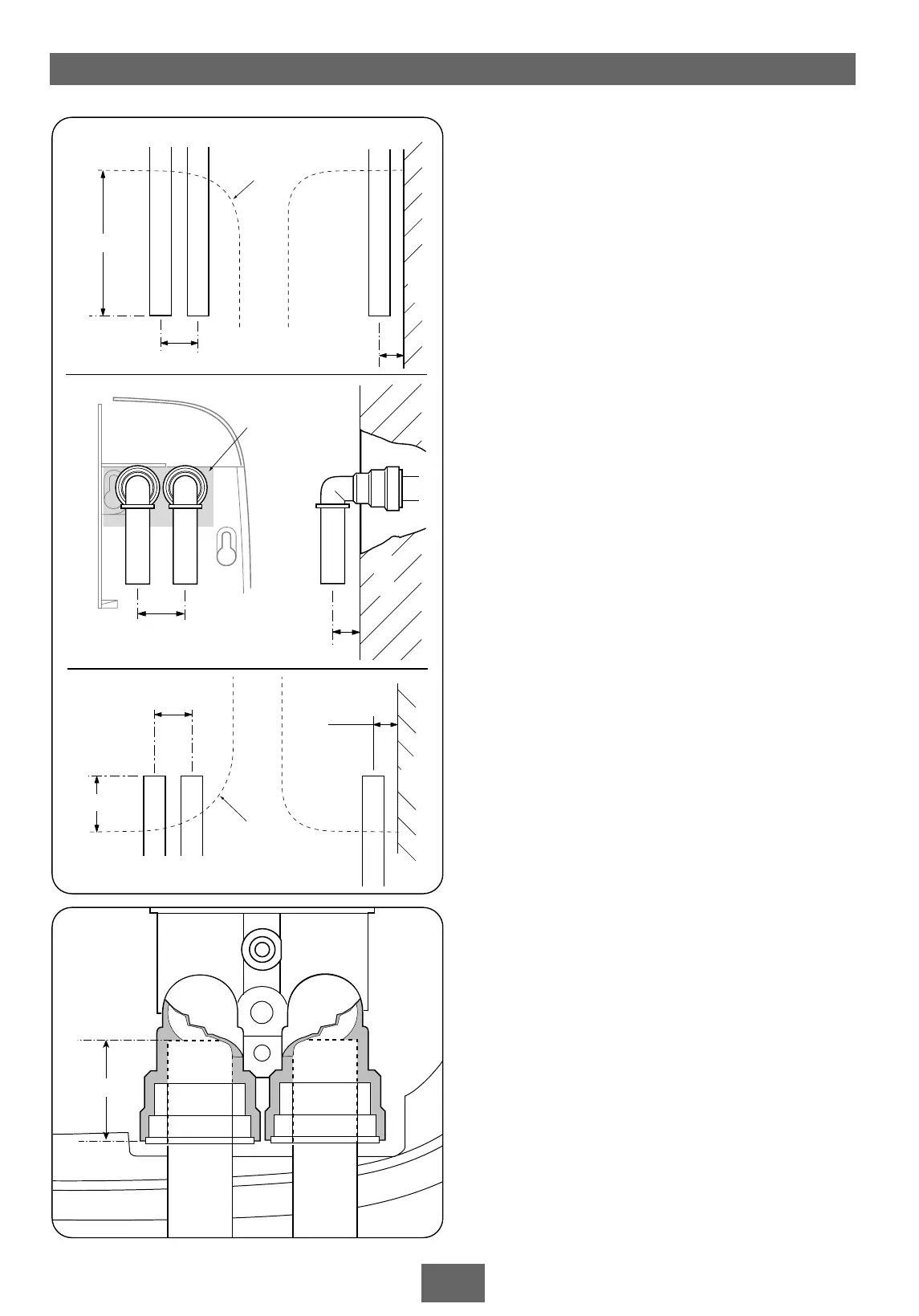
Decide the position of the shower. Cut the
pipework to the dimensions relevant to the
chosen direction of water entry into the shower.
IMPORTANT: For rear entry only, the
supplied elbows must be used. For ease of
installation, the backplate area adjacent to
the top pipe inlet must be cut out, including
the top left wall fixing hole.
When fitting the elbows to incoming pipework,
ensure the elbow collets are fully engaged with
the pipe.
Dimensions are shown in fig.9 and fig.10.
Note: The pipe inlets are marked for hot and
cold connections – left-hand side for hot inlet on
bottom entry (fig.11), but right-hand side for
hot inlet on top or rear entry (fig.12).
IMPORTANT: The fittings on the inlet elbows
are the push-in type. The pipework must be
cut with a pipe cutter and all burrs and rough
edges removed from the end of the tube. The
fittings can be used with copper and plastic
pipe.
If using chrome plated copper pipe, remove
the first 25mm of plating completely from the
connecting surfaces. If not completely removed
then the collet will not grip the pipe and
under pressure the pipe may be forced out.
Note: Pipework must be clipped or fixed to the
wall so that it cannot be moved or removed
without the aid of a tool.
Hot
19 mm
98 mm
26 mm
Wall
Cold
Rear edge
of
backplate
Fig.9
Top
19 mm
26 mm
Cold
Hot
Area of
backplate
to remove
Wall
19mm
34mm
26mm
Rear edge
of
backplate
Hot Cold
Wall
Rear
Bottom
Fig.10