ELECTRICAL CONNECTIONS
SWITCH OFF THE ELECTRICITY SUPPLY
AT THE MAINS.
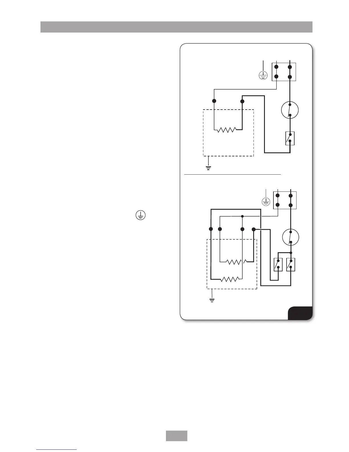
Fig.9 shows the 3kW unit and 7kW unit
schematic wiring diagrams.
The cable can be surface clipped, hidden or via
20mm conduit. For the 3kW handwash unit the
minimum cable size will be 1.5mm² and for the
7kW unit the minimum will be 6mm².
Note: The supply cable earth conductor must
be sleeved. The outer sheath of the supply cable
must be stripped back to the minimum.
Note: For top cable entry, remove sufficient
outer sheath to assist routing beneath and
looping back into the terminal block.
DO NOT
remove to much outer sheath.
Note: Conduit entry can only be from rear.
Route the cable into the unit and connect to the
terminal block
(fig.10) as follows:
Earth cable to terminal marked
E
Neutral cable to terminal marked N
Live cable to terminal marked
L
IMPORTANT: Fully tighten the terminal block
screws and ensure that no cable insulation is
trapped under the screws. Loose connections
can result in cable overheating.
The use of connections within the unit, or other
points in the circuit, to supply power to other
equipment i.e. extractor fans, pumps etc. will
invalidate the guarantee.
DO NOT switch on the electricity supply
until the cover has been fitted and the unit
commissioned.
3kW diagram
7kW diagram
1. Terminal block
2. Thermal cut-out
3. Microswitch
4. Element
Fig.9
 Loading...