T30i
12
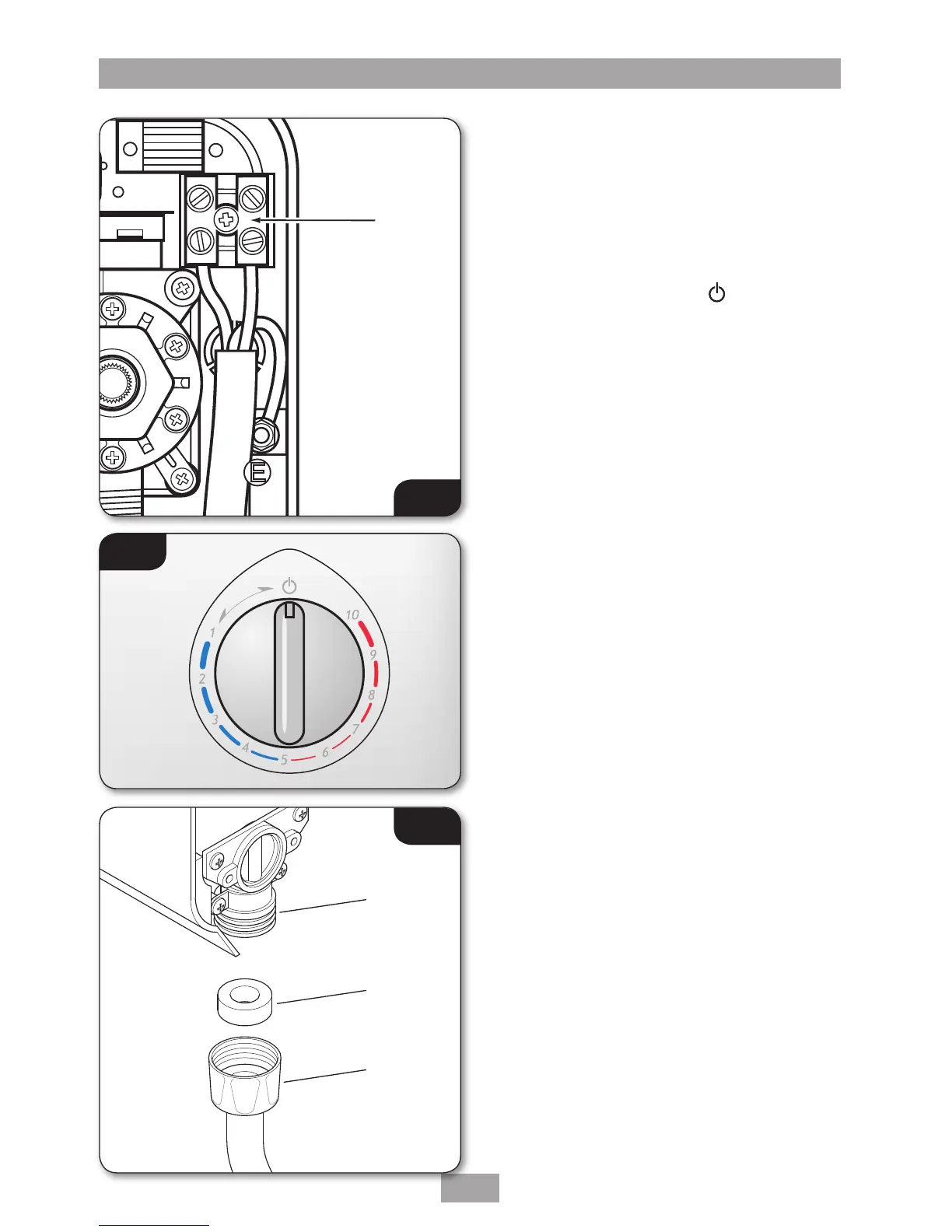
REPLACING THE COVER
To ensure that the temperature control is
correctly positioned on the stabiliser valve,
temporarily place the cover in position so that
the splines engage and rotate the temperature
control fully clockwise.
Remove the cover and position the temperature
control so that it points at the
position
(fig.11).
Replace the cover squarely to the backplate and
guide into position so that the control locates
correctly into the splined spindle. Should any
difficulty arise, recheck the points above.
Secure the cover in position with the two
retaining screws.
DO NOT switch on the electricity supply to the
unit until the commissioning procedure has
been carried out.
SWIVEL ARM FITTING
Screw the swivel arm connector onto the outlet
pipe (fig.12).
Note: It is advisable to apply PTFE tape to the
threads of the outlet pipe prior to fitting the
swivel arm in order to provide a watertight seal.
 Loading...
