17
ELECTRICAL CONNECTIONS
NOTE: The elements on UK models are to
240V specification and will give a lower kW
rating if the voltage supply is below 240V.
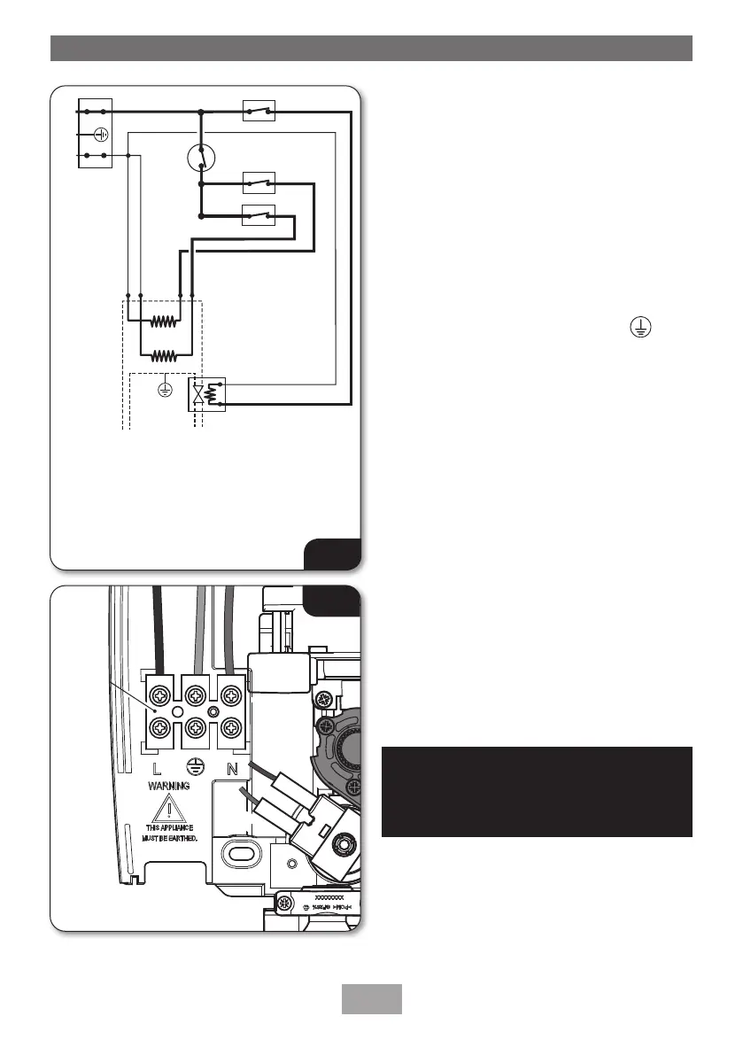
Terminal
block
Fig.14
ELECTRICAL CONNECTIONS
IMPORTANT: Switch off the electricity supply at
the mains before proceeding.
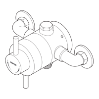
• Fig.13 shows a schematic wiring diagram.
• The cable entry points are listed on page 6.
• The cable can be surface clipped, hidden or
routed via 20mm conduit.
NOTE: Conduit entry can only be from rear.
Route the cable into the shower unit and connect
to the terminal block (g.14) as follows:
Earth cable to terminal marked
Neutral cable to terminal marked N
Live cable to terminal marked L
IMPORTANT: Fully tighten the terminal block
screws and make sure that no cable insulation is
trapped under the screws. Loose connections can
result in cable overheating.
NOTE: The supply cable earth conductor must be
sleeved. The outer sheath of the supply cable must
be stripped back to the minimum.
• The supply cable MUST be secured either by
routing through conduit, in trunking, or by
embedding in the wall, in accordance with
IEE regulations.
• The use of connections within the unit or
other points in the shower circuit to supply
power to other equipment i.e. extractor fans,
pumps, etc., will invalidate the guarantee.
• DO NOT switch on the electricity supply
until the cover has been tted.
Fig.13
1. 3 way terminal block
2. Start/Stop Microswitch
3. Power selector Microswitch
4. Solenoid valve
5. Thermal cut-out (main)
6. Element

 Loading...